Low-Latency Software · Technology
4Multi-Socket Machines and Interconnects
A trading server with two processor sockets, a network card in a slot wired to the second socket, and a strategy thread that the operating system happened to start on the first: every packet the card delivered was written near socket 1 and read from socket 0, and every order went back the other way. Each crossing costs roughly a hundred nanoseconds more than staying on one socket, several times per message, on a path whose whole software budget is a few microseconds. Nobody had chosen the placement; nobody had looked at the machine’s topology. This chapter describes the machine above the core: memory attached to sockets, the links between sockets, the bus that connects the network card, and how to read all of it from the operating system and place a trading process on it.
4.1 Non-uniform memory access
Definition 4.1 (Non-uniform memory access, NUMA node)
In a machine with non-uniform memory access (NUMA) each processor socket has its own memory controllers and memory; a core reaches its own socket’s memory faster than another socket’s, which it reaches over the socket interconnect. A NUMA node is a set of CPUs and the memory close to them, usually one socket (or part of one).
Definition 4.2 (First-touch allocation)
Under first-touch allocation, the default policy of Linux, a page of memory is placed on the NUMA node of the CPU that first writes it (the page fault that creates it), not the one that allocated the address range.
First touch makes placement a question of who initialises what. A trading process that builds its order books, rings and pools in its main thread during start-up, before creating its threads, puts all of them on the main thread’s node, wherever the hot threads later run. The rule: pin each hot thread first (chapter 9), then let it allocate and touch its own data; or bind the memory explicitly (numactl –membind, mbind).
Example 4.3 (A book allocated on the wrong node)
The main thread, on node 0, allocates and zeroes 64 MiB of order books with huge pages at start-up, then starts the feed thread on node 1. Every book update now misses to the other socket’s memory. The fix is one line: move the initialisation into the feed thread, after it has pinned itself, or pass the node to the allocator.
4.2 The socket interconnect and remote caches
Definition 4.4 (Socket interconnect)
The socket interconnect is the set of point-to-point links between the processor sockets of a machine, which carry remote memory accesses and the cache-coherence traffic between sockets.
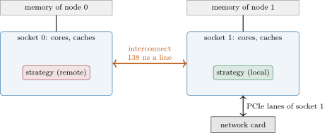
Every coherence transaction of chapter 3 that involves a line held on the other socket crosses the interconnect. A published measurement of a two-socket server of a recent Intel generation found that bouncing a cache line between two cores took 59 nanoseconds on average within a socket (81 at worst) and 138 nanoseconds across sockets; older generations were similar, up to 150 across. A hand-off between two threads, the feed handler publishing a message and the strategy reading it, is exactly such a bounce (chapter 12): placed on two sockets, it more than doubles.
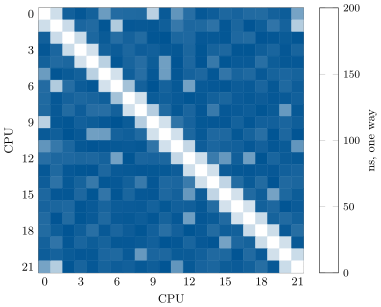
The same measurement on this book’s laptop, which has one socket and runs under a hypervisor, is Figure 4.1. It has structure: pairs of neighbouring virtual CPUs hand a line over in about 40 nanoseconds, most other pairs in 170 to 200. The laptop’s physical cores sit in clusters sharing a second-level cache, and the virtual CPUs are mapped onto them by the hypervisor, not visibly to the guest; the matrix, not the CPU numbering, is what tells which threads should talk to each other.
bench_c2c.py.4.3 The peripheral bus and direct memory access
Definition 4.5 (PCI Express, direct memory access)
PCI Express (PCIe) is the serial point-to-point bus that connects devices (network cards, storage, accelerators) to a processor socket, in lanes grouped by 1 to 16. In direct memory access (DMA) a device reads and writes host memory itself, without the processor copying each byte: a network card writes each received packet into a buffer the driver gave it and signals its arrival by a descriptor, an interrupt or a flag the program polls.
Definition 4.6 (Direct cache access)
Direct cache access lets a device’s DMA writes land in the processor’s last-level cache instead of memory, so that the core that processes the data finds it in cache; Intel’s implementation (Data Direct I/O) is transparent to software.
Every PCIe slot belongs to one socket: its lanes come from that socket’s processor. A card’s packets therefore arrive in that socket’s cache or memory, and the card’s registers, which the program writes to send, are across the interconnect from any core on the other socket. Each transaction on the bus adds its own latency, which is why low-latency network cards and their user-space drivers minimise the number of bus transactions per packet (One Quant Book 14, chapter 3).
As of September 2026 — PCI Express generations
PCIe 4.0 signals at 16 GT/s per lane and PCIe 5.0, whose specification PCI-SIG released in May 2019, at 32 GT/s; both encode 128 bits in 130. A 16-lane PCIe 5.0 link therefore carries GB/s in each direction, far more than a 100 Gb/s network port needs (12.5 GB/s): for a trading card the bus matters for its latency, not its bandwidth.
4.4 Where the network card sits
Definition 4.7 (Device locality)
The device locality of a thread or a buffer is its NUMA node relative to the device it exchanges data with: local when they are on the same node, remote otherwise.
Proposition 4.8 (Cost of remote placement)
If a message brings cache lines from the card to the hot thread and an order sends back, each transferred one after the other, and a line costs within the socket and across it, then remote placement adds to the tick-to-trade latency.
Proof. Each of the dependent transfers costs instead of ; the rest of the path is unchanged. ∎
With two lines each way and the published 59 and 138 nanoseconds, the proposition gives 316 nanoseconds per message: more than a tenth of the a very good software system takes wire to wire (chapter 1). The placement rules follow: the card, the hot threads and their memory on one node; each hot thread on its own physical core, its hyper-threading sibling idle; the interrupts of other devices and the operating system’s work on the other node or on housekeeping cores (chapter 13); and every thread that exchanges data with the hot path per message (the risk gate, the logger’s ring) on the same node.
4.5 Reading a machine’s topology
Linux exposes the topology in sysfs. Each CPU’s physical package, core and hyper-threading siblings are under /sys/devices/system/cpu/cpu*/topology/; each node’s CPUs under /sys/devices/system/node/node*/cpulist; each PCI device’s node in /sys/bus/pci/devices/*/numa_node, which holds when the firmware did not say; and the device behind a network interface is the link /sys/class/net/<name>/device. Tools such as lscpu, numactl –hardware and lstopo print the same facts; a placement plan should read them itself, so that a moved card or a new server cannot silently invalidate it.
This laptop shows what can go wrong. Linux sees one node, 22 CPUs described as eleven cores of two threads (the processor has 6 two-thread performance cores and 10 single-thread efficient cores), and a network interface that is a synthetic adapter of the hypervisor, not a PCI device: there is no card to be local to. The build of this chapter therefore treats an unknown node as a fact to report, not to guess.
4.6 Tutorial: a placement plan and the core-to-core matrix
Goal. Read a machine’s topology, place the hot threads of a trading process on it, check the plan, and measure the cost of a hand-off between every pair of CPUs. End state: a checked plan for a two-socket fixture and for this laptop, and Figure 4.1.
- Read the tree.
read_topology(root)parses the sysfs files above; the tests run it on two synthetic trees written bymake_coreplan_fixture.py(a two-socket, 32-CPU server with its card on node 1, and a one-node machine whose card’s node is unknown). Place. The hot roles take the highest-numbered physical cores of the card’s node, one each, leaving their siblings idle; CPU 0’s core and every other CPU go to housekeeping.
def plan(topo, ifname, hot=("feed", "strategy", "gateway"), cold=("logger",)):
    card = topo.card_for(ifname)
    node = card.node if card.node >= 0 else min(topo.nodes)
    cores = topo.physical_cores(node)
    # never give CPU 0's core to the hot path: the kernel and many drivers favour it
    cores = [s for s in cores if 0 not in s]
    if len(cores) < len(hot):
        raise ValueError(f"node {node} has {len(cores)} usable physical cores for {len(hot)} hot threads")
    roles, idle, used = {}, [], set()
    for role, sib in zip(hot, cores[-len(hot):], strict=True):   # take the highest-numbered cores
        roles[role] = sib[0]
        idle += list(sib[1:])
        used |= set(sib)
    house = tuple(c for c in sorted(topo.cpus) if c not in used)
    for role in cold:
        roles[role] = house[-1]
Listing 4.1. A placement plan from the topology. code/firm/coreplan/firm_coreplan.py - Check.
check(plan, topo)lists every violated rule: a hot thread on the wrong node, two hot threads on one physical core, a busy sibling, CPU 0 not in housekeeping. Measure hand-offs. Two pinned threads bounce one padded atomic flag; the time per one-way transfer is the core-to-core latency.
python bench_c2c.pyruns it for every pair.inline double one_way_ns(int cpu_a, int cpu_b, int round_trips) { firm::memkit::CachePadded<std::atomic<int>> flag; flag.value.store(0); std::atomic<bool> go{false}; std::thread b([&] { pin(cpu_b); while (!go.load(std::memory_order_acquire)) { } for (int i = 0; i < round_trips; ++i) { while (flag.value.load(std::memory_order_acquire) != 1) { } flag.value.store(0, std::memory_order_release); } }); pin(cpu_a); go.store(true, std::memory_order_release); const auto t0 = std::chrono::steady_clock::now(); for (int i = 0; i < round_trips; ++i) { while (flag.value.load(std::memory_order_acquire) != 0) { } flag.value.store(1, std::memory_order_release); } while (flag.value.load(std::memory_order_acquire) != 0) { } const auto t1 = std::chrono::steady_clock::now(); b.join(); return std::chrono::duration<double, std::nano>(t1 - t0).count() / (2.0 * round_trips); }Listing 4.2. Bouncing a cache line between two pinned threads. code/low-latency/04-multi-socket-machines-and-interconnects/cpp/ll_c2c.hpp
What to change next. Add a rule to check that the logger is on the card’s node too, and decide whether it should be; rerun the ping-pong with the flag and a payload of four lines, and compare the cost per line.
4.7 Build: the core placement plan
Purpose. One description of where every thread of the trading process runs, derived from the machine rather than typed by hand: chapter 9 pins threads from it, chapter 13 audits a host against it, chapter 26 records it with every measurement.
Interface. Python firm_coreplan: read_topology(root) returning Topology (CPUs with package, core, node and siblings; nodes; PCI cards with node and local CPUs; interfaces), Topology.card_for(ifname), plan(topo, ifname, hot, cold) returning Plan(node, roles, idle, housekeeping), check(plan, topo), remote_penalty_ns.
Rules. Hot roles on the card’s node, one physical core each, siblings idle, never CPU 0’s core; an unknown node () falls back to the lowest node and is reported; the plan fails loudly when the node has too few cores.
Acceptance tests. code/firm/coreplan/tests/: parsing CPU lists; the two-socket fixture’s topology and a sound plan on node 1; plans with a thread on the wrong socket and two threads on one core caught; the one-node fixture with an unknown card.
Stretch. Read cache topology (/sys/devices/system/cpu/cpu*/cache/) and place threads that exchange data per message on cores sharing a cache level; include the measured core-to-core matrix in the plan.
Sources and further reading
- Chips and Cheese, “Core to core latency data on large systems”, 2023.
- Linux kernel documentation, “NUMA memory policy”; ABI documentation,
sysfs-bus-pci. - Intel, “Intel Data Direct I/O technology”.
- PCI-SIG, PCI Express 5.0 specification announcement, 2019.
4.8 Exercises
Exercise 4.1 ★
What is the usable bandwidth in each direction of an 8-lane PCIe 4.0 link? Is it enough for two 25 Gb/s ports?
Solution
Solution of Exercise 4.1.
GB/s in each direction; two 25 Gb/s ports need 6.25 GB/s: yes, with room to spare.
Exercise 4.2 ★
A packet of 300 bytes lands in the cache of the card’s socket. How many cache lines must a core on the other socket fetch to read it?
Solution
Solution of Exercise 4.2.
lines if the packet starts on a line boundary, 6 if it does not.
Exercise 4.3 ★
/sys/bus/pci/devices/0000:81:00.0/numa_node contains 1 and the strategy runs on CPU 5, whose node is 0. What does Proposition 4.8 give with three lines in, one out, and the published figures?
Solution
Solution of Exercise 4.3.
The card is on node 1 and the strategy on node 0: remote. per message.
Exercise 4.4 ★★
The feed handler, pinned to node 1, publishes each message into a ring that the main thread allocated and zeroed at start-up on node 0. Where does each write go, and how do you fix it?
Solution
Solution of Exercise 4.4.
First touch put the ring’s pages on node 0, so every write from node 1 goes across the interconnect to node 0’s memory or caches, and the reader pays again if it is on node 1. Allocate and zero the ring in the feed thread after pinning it, or bind the ring’s memory to node 1.
Exercise 4.5 ★★
Read Figure 4.1: which pairs of CPUs would you give to a feed thread and a strategy thread that hand over every message, and what would a hand-off cost between the pair you chose and a random pair?
Solution
Solution of Exercise 4.5.
Two neighbouring virtual CPUs, for example 0 and 1: a hand-off of about 40 nanoseconds one way on the committed matrix, against a median of about 190 for other pairs, four to five times more. The choice holds only as long as the hypervisor’s mapping does.
Exercise 4.6 ★★
Why must a hot thread’s hyper-threading sibling stay idle, and what does the plan lose by it on the two-socket fixture?
Solution
Solution of Exercise 4.6.
The sibling shares the core’s execution units, first-level caches and predictors, so any work on it slows and jitters the hot thread. On the fixture the three hot threads leave CPUs 29, 30 and 31 idle: three of node 1’s sixteen CPUs.
Exercise 4.7 ★★★
Coding. Extend firm_coreplan.plan to place four hot threads on a node with only three usable physical cores by sharing one core between the two threads that exchange the least data. Which pair would you choose in a feed, book, strategy and gateway pipeline, and what does check need to accept?
Solution
Solution of Exercise 4.7.
Share one core between the two threads that exchange the least data per message and least often compete for it: the gateway and the book builder are poor candidates (both on every message); the pair that exchanges data only through another thread, for example the book builder and the gateway when the strategy sits between them, is the least bad. check must accept a declared pair of roles on one physical core, and nothing else.
Exercise 4.8 ★★★
Find the flaw. “We pinned our strategy with taskset -c 5 in the service’s start script, so it is on the right socket.”
Solution
Solution of Exercise 4.8.
taskset pins the thread but says nothing about the card: nobody checked that CPU 5 is on the card’s node, the choice breaks when the server or the slot changes, the process’s memory may have been first touched elsewhere, and threads created later inherit the mask rather than getting their own cores. Derive the placement from the topology and check it at start-up.
4.9 Problem: Wrong Socket
Problem 4.1
Weekend problem — a server nobody had looked at
A firm’s new two-socket server has its network card on node 1. The feed handler, strategy and gateway were started by a script without any pinning, and the scheduler put them on node 0. Each market-data message brings two cache lines to the strategy; each order sends two lines to the card. Take the published figures: 59 nanoseconds per line within a socket, 138 across.
Part I — The topology.
- Which sysfs files tell the node of the card and of each CPU?
- On the fixture
two_socket, which CPUs are on node 1, and what are the siblings of CPU 17? - What does
planreturn for the three hot roles, and which CPUs does it leave idle? - Why does the plan never use CPU 0’s core?
Part II — The penalty.
- Apply Proposition 4.8: what does the wrong socket add per message?
- What fraction of a wire-to-wire budget is that?
- If the strategy also reads its order book, allocated by the main thread on node 0, what happens when the threads are moved to node 1 without moving the book?
- Which of the two mistakes is worse, and why?
Part III — Hand-offs.
- The feed thread hands every message to the strategy through a ring: one line each way. What does the hand-off cost within a socket and across?
- On this laptop, what does it cost between neighbouring CPUs and between others (Figure 4.1)?
- How would you choose the two CPUs from the matrix alone?
- Why can the matrix change from one boot of a virtual machine to the next?
Part IV — The fix.
- State the named result: the latency added per message by the wrong socket, in nanoseconds and as a share of a budget.
- Write the steps of the fix, in order.
- How do you verify after the fix that each thread runs where the plan says?
- What should happen when a hardware change moves the card to node 0?
- Which other devices’ interrupts should be moved away from the hot cores?
- What does
numa_nodemean, and what should the plan do? - What would you record with every latency measurement so that a placement change is visible later?
- In one sentence: why is placement a latency decision?
Solution
Solution of Problem 4.1.
/sys/bus/pci/devices/<address>/numa_nodefor the card (found from/sys/class/net/<name>/device), and/sys/devices/system/node/node*/cpulistfor the CPUs.- CPUs 16 to 31; CPU 17’s siblings are 17 and 25.
- Feed on 21, strategy on 22, gateway on 23; CPUs 29, 30 and 31 idle.
- The kernel, timers and many drivers favour CPU 0; keeping its core for housekeeping keeps that work off the hot path.
- .
- .
- Each book access now misses to node 0’s memory across the interconnect: the threads are local to the card but their data is remote.
- The book: its accesses are many per message and dependent (a tree or ladder walk), while the card’s lines are few.
- One line each way: within a socket, across.
- About 40 nanoseconds one way between neighbouring CPUs and about 190 between the others, on the committed measurement.
- Choose the pair with the lowest measured hand-off, among CPUs on the card’s node, and verify it after every boot.
- The hypervisor maps virtual CPUs to physical cores as it sees fit, and the mapping can differ between boots or change while running.
- Named result. The wrong socket adds about per message, 12.6% of a wire-to-wire budget, before counting data first touched on the wrong node.
- Read the topology; compute the plan; pin each hot thread before it allocates; allocate and touch its memory from it; move other devices’ interrupts off the hot cores; check the plan at start-up and refuse to trade if it fails.
- Read each thread’s CPU (
/proc/<pid>/task/*/statorsched_getcpulogged by the thread) and each region’s node (/proc/<pid>/numa_maps) and compare with the plan. - The plan is recomputed from the topology and the process moves with the card; a start-up check catches it if nobody does.
- Those of the disks, other network cards, and timers; the card’s own interrupts, if it uses them, go to the node’s housekeeping cores.
- The firmware did not report the card’s node: the plan falls back to a default and must say so, and a human must confirm.
- The placement plan (the topology, each thread’s CPU and node), with the machine and software versions.
- Because where a thread and its data sit decides how many interconnect crossings each message pays.
4.10 Interview questions
Interview question 4.1 ★ developer
What is NUMA, and what does it mean for a latency-sensitive process?
Solution
Solution of Interview question 4.1.
Each socket has its own memory; memory attached to another socket is slower to reach over the interconnect. A latency-sensitive process must keep its hot threads, their memory and the network card on one node.
What the interviewer is looking for: local versus remote memory and the placement consequence.
Interview question 4.2 ★★ developer
What is first-touch allocation, and how can it put a thread’s memory on the wrong node?
Solution
Solution of Interview question 4.2.
Linux places a page on the node of the CPU that first writes it; if the main thread initialises the data at start-up and the worker runs on another node, the worker’s data is remote. Pin first, then touch, or bind explicitly.
What the interviewer is looking for: that initialisation, not allocation, decides placement.
Interview question 4.3 ★★ developer
How do you find which socket a network card is attached to on Linux?
Solution
Solution of Interview question 4.3.
Find its PCI address from /sys/class/net/<if>/device, then read numa_node and local_cpulist under /sys/bus/pci/devices/<address>/; lstopo shows it graphically.
What the interviewer is looking for: sysfs, and awareness that means unknown.
Interview question 4.4 ★★ developer
Two threads exchange a message a microsecond. Where would you place them on a two-socket machine, and why?
Solution
Solution of Interview question 4.4.
On the same socket, ideally on cores that share a cache level, each on its own physical core with siblings idle, on the network card’s node: a hand-off across sockets costs more than twice as much.
What the interviewer is looking for: core-to-core latency as the cost of a hand-off.
Interview question 4.5 ★★ developer
What is DMA, and what does direct cache access change for a packet’s path to the application?
Solution
Solution of Interview question 4.5.
The card writes packets into host memory by itself, without the processor copying them; with direct cache access they land in the last-level cache of the card’s socket, so the core reading them hits in cache instead of memory, provided the core is on that socket.
What the interviewer is looking for: device-driven transfers and their locality.
Interview question 4.6 ★★★ developer
Design a start-up procedure for a trading process that guarantees correct placement of its threads and memory on any server in the fleet.
Solution
Solution of Interview question 4.6.
At start-up, read the topology; derive each thread’s CPU from the card’s node by a fixed rule (one physical core each, siblings idle, CPU 0 excluded); pin each thread before it allocates; allocate and touch its memory from it or bind it; verify the placement from /proc and refuse to trade on a mismatch; log the plan with every measurement.
What the interviewer is looking for: derived rather than hand-typed placement, and a check that refuses to start.