 Coach
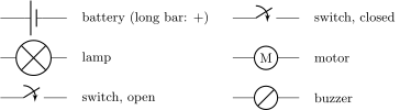
CoachA circuit diagram is the standard drawing of a circuit: each device is shown by its agreed symbol, and the wires by straight lines drawn with square corners. A diagram shows how the circuit is connected — who feeds whom, what forks where — and deliberately ignores how the real wires snake across the table.
Examples
Example 41.3 (Same circuit, two portraits)
On the table: a battery, a tangle of alligator-clip wires looping over a pencil case, a lamp leaning on a book, a switch dangling. On paper: a calm rectangle — battery on the left, switch on top, lamp on the right. The tangle and the rectangle are the same circuit: every connection identical. To decide whether two circuits are the same, ask one question only: who is connected to whom?
Example 41.4 (Motors and buzzers join the game)
Two newcomers to your kit behave just like lamps in a diagram: the motor (symbol: M in a circle) spins whenever current flows through it — fans, toy cars, drills; the buzzer (a struck circle) sounds whenever fed — doorbells, alarms. Series and parallel rules apply to them unchanged: a switch in series commands them; parallel branches make them independent.