Inside a loudspeaker cabinet a coil and a capacitor decide, without a single transistor, that the bass goes to the big cone and the treble to the small dome. An oscilloscope’s “AC” button removes a slowly drifting offset and keeps the wiggle on top of it. A power supply turns a pulsating rectified mains into a steady voltage with one capacitor. All three are filters: linear circuits that treat each frequency differently. Because any periodic signal is a sum of sinusoids, knowing what a circuit does to every sinusoid — its transfer function — is knowing what it does to everything. This chapter defines transfer functions, draws their Bode diagrams for the first- and second-order circuits of the previous chapters, and uses them to predict how a square wave comes out of a filter.
9.1 Transfer function and Bode diagram
Definition 9.1(Transfer function)
A linear circuit with an input voltageUe and an output voltageUs (taken with nothing connected at the output) has the transfer function
H(jω)=UeUs,G(ω)=∣H∣,φ(ω)=argH,
the gainG (ratio of amplitudes) and the phase shift φ of the output relative to the input. A filter is such a circuit used for its frequency dependence: a sinusoid of amplitudeE at ω comes out as G(ω)Ecos(ωt+φ(ω)).
Definition 9.2(Decibels; Bode diagram)
The gain in decibels is GdB=20log10G: a factor 10 is 20dB, a factor 2 is 6dB, 1/2 is −3dB. The Bode diagram plots GdB and φ against log10ω (or f). The cutoff frequency is where G falls to Gmax/2 (−3dB from the maximum); the passband is the range of frequencies within 3dB of the maximum. A decade is a factor 10 in frequency, an octave a factor 2.
Method 9.3(Nature of a filter at a glance)
Before computing, look at the limits: at very low frequency a capacitor is an open circuit and a coil a wire; at very high frequency the reverse. Replace each and read whether the output is the input (passes) or zero (blocked). Passes low, blocks high: low-pass; the reverse: high-pass; blocks both: band-pass; passes both: band-stop. Then compute H by a voltage divider.
9.2 First-order filters
Proposition 9.4(First-order low-pass)
The RC divider with output across C (or the RL divider with output across R) has
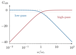
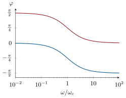
Bode asymptotes: GdB=0 for ω≪ωc, a straight line falling 20dB per decade for ω≫ωc, meeting at ωc where the true curve is −3dB and φ=−45∘. For ω≫ωc, H≈ωc/(jω): the output is proportional to the integral of the input — the filter is an integrator there.
Far above cutoff, 1+jω/ωc≈jω/ωc, and dividing a complex amplitude by jω is integrating (Proposition 8.3): us≈ωc∫uedt. 20log(ωc/ω) loses 20dB per tenfold ω. ∎
Proposition 9.5(First-order high-pass)
The CR divider with output across R (or LR with output across L) has
rising 20dB per decade below ωc, flat above, −3dB and +45∘ at ωc. For ω≪ωc, H≈jω/ωc: the output is proportional to the derivative of the input.
Proof.H=R/(R+1/jCω)=jRCω/(1+jRCω); multiplying by jω is differentiating. ∎
Bode diagrams of the first-order low-pass (blue) and high-pass (red): gain in decibels with the asymptotes (dashed) meeting at the cutoff, where the true gain is −3dB, and phase, which crosses ∓45∘ at the cutoff.
Example 9.6(AC coupling)
An oscilloscope’s AC input is a high-pass with fc≈10Hz: a 1kHzsignal riding on a 5V offset comes through at −0.0002dB with its offset removed. But a 50Hz square wave is visibly distorted — its flat tops sag — because at 50Hz the filter is only one decade above its cutoff and the signal’s low harmonics are shifted in phase (Exercise 9.12).
9.3 Second-order filters
Proposition 9.7(The series RLC as three filters)
With x=ω/ω0, ω0=1/LC and Q=L/C/R, the series RLC fed by Ue gives, according to where the output is taken:
across C:across R:across L:H=1−x2+jx/Q1,H=1−x2+jx/Qjx/Q=1+jQ(x−1/x)1,H=1−x2+jx/Q−x2:
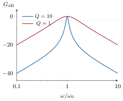
a low-pass, a band-pass and a high-pass of second order. Far from ω0 the low-pass and high-pass fall by 40dB per decade, the band-pass by 20dB per decade on each side; the band-pass has its maximum 1 at ω0 and the bandwidth Δω=ω0/Q of Theorem 8.9.
Proof.Voltage dividers with the total impedanceR+j(Lω−1/Cω); multiply numerator and denominator by jCω and use LCω02=1, RCω0=1/Q. The band-pass is the current resonance of the previous chapter read as a voltage across R. ∎
Proposition 9.8(Second-order low-pass: the role of Q)
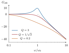
For the low-pass, G=1/(1−x2)2+x2/Q2: for Q>1/2 the gain rises above 1 near ω0 (resonance, peak ≈Q for large Q); for Q=1/2 it is “maximally flat”, G=1/1+x4, exactly −3dB at ω0; for smaller Q it droops early. The phase runs from 0 to −π, through −π/2 at ω0.
Proof.(1−x2)2+x2/Q2=1+x4+x2(1/Q2−2): the middle term vanishes for Q2=21, is negative (peak) above, positive (droop) below; the behavior near x=1 was analyzed in Proposition 8.10. ∎
Second-order filters from the series RLC. Left, the low-pass (output across C) for three Q: a resonance peak, the maximally flat response, or an early droop, all joining the −40dB/decade asymptote (dashed). Right, the band-pass (output across R): a peak of width ω0/Q falling 20dB/decade on each side.
Example 9.9(A crossover)
A loudspeaker’s woofer and tweeter, each 8Ω, share the amplifier through a low-pass (a series coil) and a high-pass (a series capacitor) cut at 2kHz: L=R/ωc=0.64mH, C=1/Rωc=10µF. At 2kHz each driver gets −3dB, i.e. half the power, and GL2+GH2=1 at every frequency: the power is shared, not lost. The weekend problem designs a steeper version.
9.4 Filtering a periodic signal
Theorem 9.10(Fourier decomposition)
A periodic signal of period T=2π/ω (reasonably regular) is the sum of a constant and of sinusoids at the multiples of ω:
s(t)=c0+n=1∑∞cncos(nωt+φn),
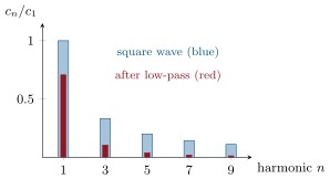
where c0=⟨s⟩ is its average value; the term n=1 is the fundamental, the others the harmonics, and the amplitudescn form the spectrum. A square wave of amplitude±E has cn=4E/(nπ) for odd n and 0 for even n; a triangle wave of amplitude±E has cn=8E/(nπ)2 for odd n.
Proof.Admitted at this level.∎
Remark 9.11(What to take from it)
The theorem and the computation of the cn belong to the Year 2 mathematics course. Here it is a tool: sharp corners need many harmonics (the square wave’s fall off only as 1/n), smooth signals need few (the triangle’s as 1/n2). A signal’s harmonic content is what an instrument’s timbre is made of, and what a filter acts on.
Proposition 9.12(Linear filtering of a periodic signal)
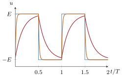
A square wave through a first-order low-pass. Left: its spectrum (odd harmonics in 1/n) and the spectrum after a filter cut at the fundamental. Right: the time signal for ωc=ω (red, exponential arcs) and ωc=10ω (orange, rounded corners only); with ωc≪ω the output would be a small triangle around the average.
Example 9.13(Numbers)
A 1kHz square wave of amplitude5V: harmonics of 6.37V at 1kHz, 2.12V at 3kHz, 1.27V at 5kHz. Through an RC low-pass cut at 10Hz (τ=16ms) the output is a triangle of amplitudeET/4τ≈80mV around zero; through a band-pass tuned to 3kHz with Q=20, a 2.1V sinusoid at 3kHz with only a few percent of the neighbors (Exercise 9.8).
9.5 Cascading filters
Proposition 9.14(Cascade and loading)
Two filters in cascade have H=H1H2 — gains multiply, decibels and phases add — provided the second does not load the first, i.e. draws negligible current from its output. Otherwise the divider relations must be rewritten for the combined network. An operational-amplifier follower (Chapter 10) between stages makes the product rule exact.
Proof.H1 was defined with an open output; if the next stage’s input impedance is much larger than the first stage’s output impedance (its Thévenin resistance), the output voltage is unchanged and the second stage sees exactly Us1 as its input. ∎
Example 9.15(Two RC stages)
Two identical RC low-passes back to back do not give 1/(1+jω/ωc)2: the second stage’s R loads the first. The exact result is H=1/[1−(ω/ωc)2+3jω/ωc], −9.5dB at ωc instead of the −6dB the product rule promises, though both reach the same −40dB/decade slope eventually.
9.6 Exercises
Exercise 9.1★
Convert to decibels: gains0.5, 10, 1/2, 100. Convert to ratios: −40dB, +6dB. Two filters in cascade (no loading) give −6dB and −20dB at some frequency: overall gain?
Solution
Solution of Exercise 9.1.
0.5→−6.0dB; 10→20dB; 1/2→−3.0dB; 100→40dB. −40dB→0.01; +6dB→2.0. Cascade: −6−20=−26dB, a ratio 0.05.
Without computing, give the nature (low-, high-, band-pass) of: (a) R in series, C across the output; (b) C in series, R across the output; (c) L in series, C across the output; (d) L and C in series, R across the output.
Solution
Solution of Exercise 9.3.
(a) low-pass (C shorts the output at high f); (b) high-pass (C opens at low f); (c) second-order low-pass (L opens at high f, C shorts); (d) band-pass (C blocks low f, L blocks high f).
Exercise 9.4★
A 1.0kHz square wave of amplitude5.0V: give the frequencies and amplitudes of its first three non-zero harmonics. Why does it have no even harmonics?
Solution
Solution of Exercise 9.4.
4E/nπ: 6.37V at 1kHz, 2.12V at 3kHz, 1.27V at 5kHz. The square wave is antisymmetric about a half-period shift (s(t+T/2)=−s(t)), which even harmonics are not.
Exercise 9.5★★
A CR high-pass cut at 10kHz receives a triangle wave of amplitude1.0V at 100Hz. Explain why it behaves as a differentiator and give the shape and amplitude of the output.
Solution
Solution of Exercise 9.5.
At 100Hz and its useful harmonics, ω≪ωc: H≈jω/ωc, a derivative divided by ωc. The triangle’s slope is ±4Ef=±400V/s, so the output is a square wave of amplitude400/(2π×104)=6.4mV.
Exercise 9.6★★
An RC low-pass cut at 10Hz receives a 1.0kHz square wave of amplitude±1.0V. Show that the output is a triangle and compute its amplitude.
Solution
Solution of Exercise 9.6.
ω≫ωc: us≈(1/τ)∫uedt, τ=1/(2π×10)=16ms. The integral of ±E is a triangle rising by ET/2 per half period: swing ET/2τ, amplitudeET/4τ=1.0×10−3/(4×0.016)=16mV around zero.
Exercise 9.7★★
A series RLC low-pass with L=10mH, C=100nF: give f0; find R for the maximally flat response; give the gain in decibels at f0 and at 10f0.
Solution
Solution of Exercise 9.7.
f0=5.03kHz. Q=L/C/R=1/2: R=2×316=447Ω. At f0: −3dB; at 10f0: 1/1+104→−40dB.
Exercise 9.8★★
A band-pass (Q=20) tuned to 3.0kHz receives the 1kHz square wave of Exercise 9.4. Compute the gain at 1, 3 and 5kHz, and the output amplitudes of these harmonics; describe the output.
Solution
Solution of Exercise 9.8.
G=1/1+Q2(x−1/x)2 with x=f/3: 1kHz: x=1/3, Q(x−1/x)=−53, G=0.019; 3kHz: G=1; 5kHz: x=5/3, 21, G=0.047. Output: 2.1V at 3kHz, with 0.12V at 1kHz and 0.06V at 5kHz — a nearly pure 3kHz sinusoid.
Exercise 9.9★★
Two identical RC low-passes (R=1.0kΩ, C=159nF) in cascade. Compute the exact transfer function (the second loads the first) and the gain at ωc=1/RC; compare with the product of the two separate gains.
Solution
Solution of Exercise 9.9.
Nodes: with a=jRCω, the first capacitor sees R upstream and R+1/jCω downstream: H=1/(1+3a+a2), i.e. 1/[1−(ω/ωc)2+3jω/ωc]. At ωc: 1/3j, G=1/3, −9.5dB; the product of two separate gains would be 1/2, −6dB. fc=1.0kHz.
Exercise 9.10★★★
Sketch the Bode asymptotes of H=(1+jω/ω1)/(1+jω/ω2) with ω1=100rad/s, ω2=1×10⁴rad/s: slopes, corners, the high-frequency plateau in decibels, and the phase at ω1ω2.
Solution
Solution of Exercise 9.10.
Below ω1: 0dB; between ω1 and ω2: rising 20dB/decade; above ω2: flat at 20log(ω2/ω1)=40dB. Phase arctan(ω/ω1)−arctan(ω/ω2): at ω=103, arctan10−arctan0.1=84∘−6∘=78∘.
Exercise 9.11★★★
A full-wave rectified sine (50Hz mains) has average 2E/π and a first harmonic at 100Hz of amplitude4E/3π. An RC low-pass must reduce the 100Hz ripple below 1% of the average: find the required cutoff frequency and time constant. Why is a capacitor alone (with the load resistance) the usual choice?
Solution
Solution of Exercise 9.11.
Far above cutoff, G≈fc/f; the ripple ratio after filtering is
2E/π(4E/3π)(fc/100)=32100fc<0.01,
so fc<1.5Hz and τ=1/2πfc>0.1s. The load itself is the R: a capacitor across it costs nothing in voltage drop and power, whereas a series resistor would waste both.
Exercise 9.12★★★
The AC coupling of an oscilloscope is a high-pass with C=0.10µF and R=160kΩ. Compute fc. A square wave is applied: show that each flat top becomes a decaying exponential and compute the sag (fraction lost over a half period) at 50Hz and at 1kHz.
Solution
Solution of Exercise 9.12.
fc=1/(2πRC)=1/(2π×1.6×105×10−7)=10Hz, τ=RC=16ms. During a flat top the capacitor charges through R: the output decays as e−t/τ from each edge. Sag over T/2: 1−e−T/2τ: 50Hz (T/2=10ms): 1−e−0.63=47%; 1kHz (T/2=0.5ms): 3%.
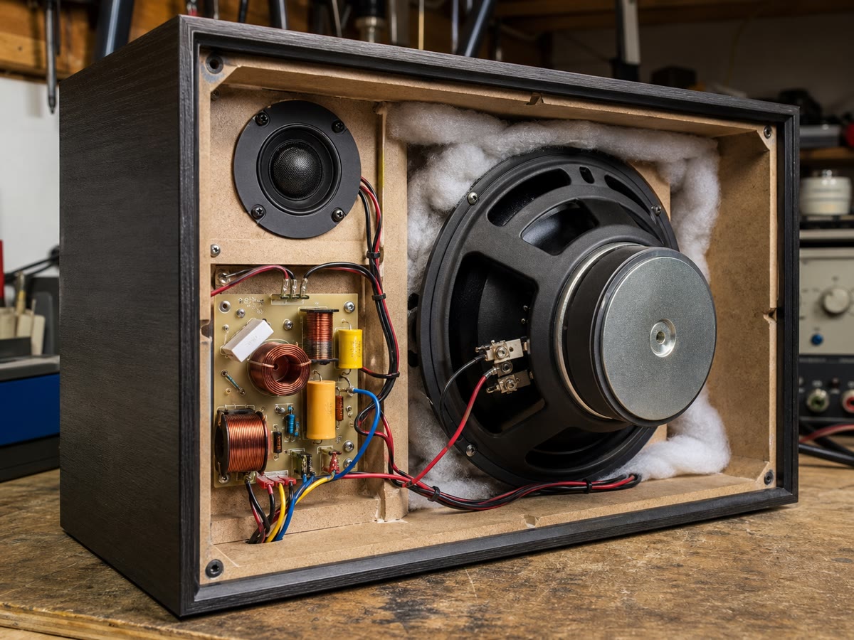
Inside a two-way loudspeaker: the crossover’s coils and capacitors are the low-pass and high-pass filters that send bass to the woofer and treble to the tweeter.
9.7 Problem: The loudspeaker crossover
Problem 9.1
Weekend problem — a woofer, a tweeter, a coil and a capacitor: how a passive crossover splits the music, why the simplest one leaks bass into the tweeter, and what a real voice coil does to the design
The woofer and the tweeter are first modeled as pure resistances R=8.0Ω. The amplifier is an ideal voltage sourceUe. The crossover frequency is fc=2.0kHz.
Part I — First-order crossover. The woofer is fed through a series coil L, the tweeter through a series capacitor C.
Show that the woofer branch is a first-order low-pass and give its cutoff ωc in terms of R and L.
Compute L for fc=2.0kHz.
Show that the tweeter branch is a first-order high-pass; give ωc and compute C.
Give each driver’s gain in decibels at fc, at 200Hz and at 20kHz.
Show that GL2+GH2=1 at every frequency. What does this mean for the power drawn from the amplifier?
Give the phase of each branch at fc; by how much do the two drivers’ voltages differ in phase there?
What are the slopes of the two responses, in dB per octave, far from fc?
Part II — Second-order crossover. The woofer is now fed through a series coil L with a capacitor C in parallel with the driver.
Show that H=1/(1−LCω2+jLω/R).
Identify ω0 and Q in terms of L, C, R.
For Q=1/2 show that G=1/1+(ω/ω0)4 and that the gain is −3dB at ω0.
Compute L and C for f0=2.0kHz and Q=1/2.
Compute the gain in decibels at 4kHz and 8kHz; deduce the slope in dB per octave.
The tweeter branch swaps the roles of L and C (series C, shunt L): write its transfer function without new calculation.
Compute the phase of each branch at f0. What must be done to the tweeter’s wiring, and why?
Part III — Music through the crossover.
A cello note at 220Hz carries harmonics up to the 20th. Which harmonics go mostly to the tweeter, with the first-order crossover?
What happens to the 9th harmonic?
A 1.0kHz square wave is used as a test signal. With the first-order crossover, give the gain of each branch for its fundamental, third and fifth harmonics.
The amplifier develops a 1V DC offset by accident. Which driver is protected, and by what?
With the first-order crossover, what fraction of the voltage and of the power of a 500Hz tone reaches the tweeter? Same with the second-order. Why does this matter for the tweeter’s survival?
Part IV — A real voice coil. The woofer is actually R=8.0Ω in series with a voice-coil inductance Lvc=0.50mH.
Compute the woofer’s impedance (modulus) at 2kHz and at 8kHz.
Recompute the first-order woofer gain at 2kHz and 8kHz with this impedance, and compare with the ideal −3dB and −12.3dB. What happened to the roll-off?
A “Zobel network” — Rz=R in series with Cz=Lvc/R2 — is connected in parallel with the woofer. Show that the combination behaves as a pure resistance R at all frequencies, and compute Cz.
The amplifier delivers 50W into 8Ω: what rms voltage is that, and what power does each driver receive at fc (first-order crossover)? At 500Hz, how much reaches the tweeter?
Summarize the trade-offs: slope, phase, component count, protection of the tweeter, and the need for a Zobel network.
13.x=2: 1/17, −12.3dB; x=4: 1/257, −24.1dB: 12dB per octave.
14. Exchanging L and C exchanges x↔1/x (and Q stays): HH=−x2/(1−x2+jx/Q).
15. At x=1: HL=Q/j=−jQ (−90∘), HH=jQ (+90∘): the drivers are in phase opposition at the crossover and would cancel acoustically; the tweeter is wired with its polarity reversed.
16. Harmonics above 2kHz: n≥10 (2.2kHz and up) go mostly to the tweeter.
19. The tweeter: its series capacitor blocks DC. The woofer takes the offset (1V across 8Ω: 125mA, 0.125W of heat and a displaced cone).
20. First order, x=0.25: GH=0.25/1.0625=0.24 (−12dB), power fraction 6%. Second order: 0.0625/1+0.0039=0.06 (−24dB), 0.4%. A tweeter rated a few watts receives 6% of a loud bass note with the first-order design — it can burn.
22.H=Z/(Z+jLω): 2kHz: 10.2/∣8+14.3j∣=10.2/16.4=0.62 (−4.2dB); 8kHz: 26.3/∣8+57.3j∣=0.45 (−6.9dB) instead of −12.3dB: the rising coil impedance fights the series coil, and the roll-off flattens to a few dB per octave.
23.Admittances: 1/(R+jLvcω)+jCzω/(1+jRCzω); with Cz=Lvc/R2 the second term is jLvcω/[R(R+jLvcω)], and the sum is (R+jLvcω)/[R(R+jLvcω)]=1/R. Cz=0.50×10⁻³/64=7.8µF.
24.U=PR=400=20V rms. At fc each driver gets half: 25W. At 500Hz the tweeter gets 6%: 3W.
25. First order: two parts, power-complementary, gentle 6dB/oct slopes, 90∘ between drivers, bass leaks into the tweeter. Second order: four parts, 12dB/oct, 180∘ at crossover (invert the tweeter), far better tweeter protection. Either way the woofer’s inductance must be tamed by a Zobel network for the design to hold.