University Physics — Year 1 · Bachelor Year 1
29Electromagnetic Induction and Applications
Move a magnet toward a coil and a current flows in the coil; stop the magnet and the current stops. Faraday found this in 1831, after ten years of looking, and it is the fact on which the electrical world runs: every power station, every transformer, every motor and loudspeaker and microphone, every induction cooktop and wireless charger converts energy through the law that a changing magnetic flux drives an electromotive force. This chapter states the law with its signs, gives it the two faces it wears (a changing field in a fixed circuit, a circuit moving in a fixed field), defines self and mutual inductance, and then works through the electromechanical machines — the sliding bar, the alternator, the transformer, the loudspeaker — where the same law turns mechanical power into electrical power and back, never for free.
29.1 Faraday’s law
Definition 29.1 (Magnetic flux through a circuit)
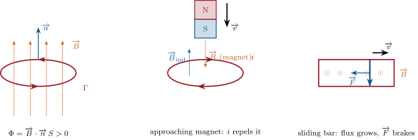
Orient a closed circuit (a sense of travel); its surface gets the normal given by the right-hand rule. The magnetic flux through the circuit is over any surface bounded by (weber, ) — “any”, because the flux of through a closed surface is zero. For a uniform field and a plane coil of turns and area , , the angle between and .
Theorem 29.2 (Faraday’s law of induction)
Whenever the flux through a circuit varies, the circuit is the seat of an induced electromotive force
counted in the orientation of the circuit, i.e. acting as an ideal voltage source of emf in that sense; in a circuit of resistance it drives the current . The minus sign is Lenz’s law: the induced current flows so as to oppose the change of flux that produces it — its own field, and the forces it feels, fight the cause.
Proof. Admitted at this level. ∎
Remark 29.3 (Two faces of the same law)
The flux changes either because varies in time through a fixed circuit (Neumann induction: transformer, induction cooktop) or because the circuit moves or deforms in a steady field (Lorentz induction: generator, loudspeaker). In the second case the emf can also be computed directly: the carriers of a conductor element moving at feel the force , equivalent to an electric field , so that — and this always agrees with . Faraday’s law covers both; the Year 2 volume explains why the two mechanisms give one formula.
Example 29.4 (Orders of magnitude)
A coil of turns and in the Earth’s field, flipped in : , — measurable with a sensitive galvanometer, the way the Earth’s field was once mapped. The same coil in the gap of a magnet, pulled out in : . A transformer coil of turns with at over : — the mains.
29.2 Self and mutual inductance
Definition 29.5 (Inductance)
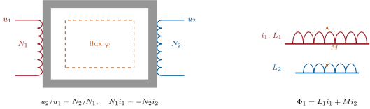
The flux of a circuit’s own field through itself is proportional to its current: , with its self-inductance (henry, ). The flux that circuit 1 sends through circuit 2 is , and symmetrically , with their mutual inductance (sign fixed by the orientations). The total flux of circuit 1 is then .
Proposition 29.6 (The inductor; the solenoid)
A circuit of inductance carrying a varying current is the seat of the emf : in the receiver convention this is the voltage of the inductor used since Chapter 7. It stores the energy . A long solenoid of turns per metre, length , section , has ; its stored energy is : magnetic energy lives in the field at the density , exactly as electric energy at .
Proof. Faraday with , constant. Energy: the power received by the inductor is . Solenoid: inside, flux through each of the turns, so . The general density is admitted. ∎
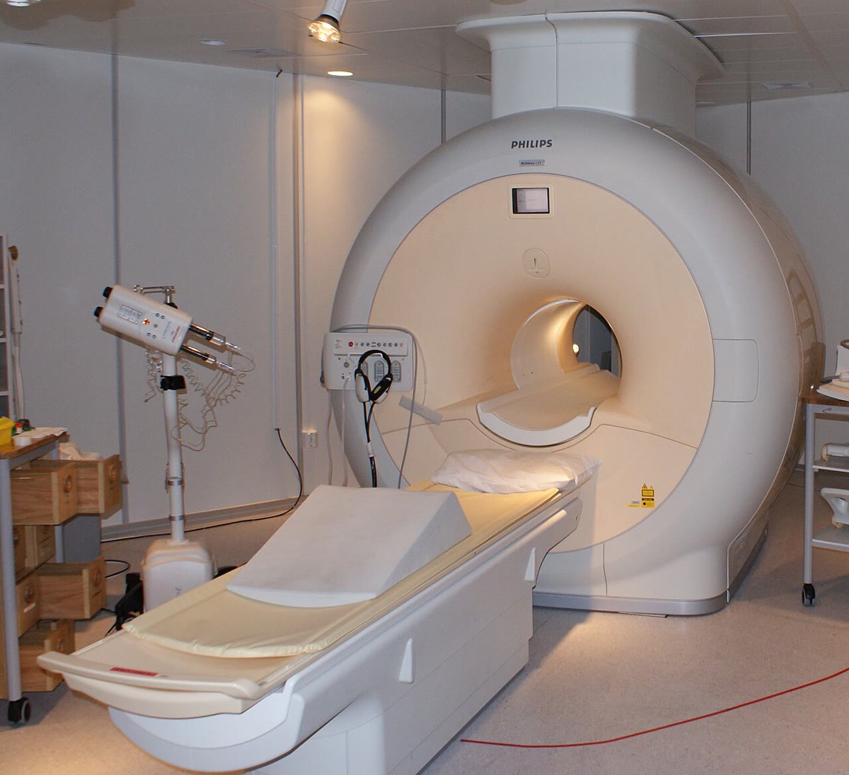
Example 29.7 (An MRI magnet)
over about a cubic metre: — the energy of a car battery, stored in empty space. With a coil current of , . If the superconductor suddenly turns resistive (a quench), that megajoule becomes heat in seconds and boils off hundreds of litres of liquid helium: the magnet room has a vent for it.
Proposition 29.8 (The ideal transformer)
Two coils of and turns wound on the same closed iron core, so that the same flux threads every turn, obey
so that : the power taken at the primary is delivered at the secondary; voltages step with the turns ratio, currents inversely. It works only with varying currents.
Proof. and (receiver convention on both, orientations chosen along the common flux): divide. The current relation is Ampère’s law on the core: its circulation -times the total ampere-turns would have to create the flux; for an ideal core () that takes vanishing ampere-turns, hence . Admitted in this form. ∎
29.3 Moving conductors: generators and motors
Proposition 29.9 (The sliding bar)
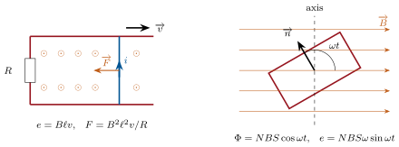
A bar of length slides at speed on two rails closed by a resistance , in a uniform field normal to the plane. It is the seat of the emf , drives , and feels the Laplace force opposing its motion. The mechanical power spent to push it, , equals the electrical power dissipated: the bar is a generator. Fed instead by a source , it is a motor: the current pushes it until the back-emf balances , at the no-load speed .
Proof. Flux , in the orientation for which is along ; the Laplace force on the current so oriented points against (Theorem 29.2, Lenz). Multiply the electrical equation by and the mechanical one by : . The electromechanical power and the Laplace power are always opposite — the law of the conversion. ∎
Proposition 29.10 (The rotating loop: alternator)
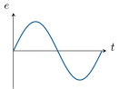
A coil of turns and area rotating at about an axis perpendicular to a uniform has and
a sinusoidal emf of amplitude and the frequency of rotation. Into a resistance it delivers the mean power , supplied by the torque that keeps it turning against the Laplace couple of its own current.
Proof. Differentiate the flux; . The couple is Theorem 28.14 with ; its mean power equals by the same computation as for the bar. ∎
Example 29.11 (Eddy currents)
A bulk conductor moving in a non-uniform field, or sitting in a varying one, is threaded by changing flux along countless closed paths: eddy currents circulate in it, heating it and — by Lenz — braking it. A magnet dropped down a copper tube drifts down slowly; the brakes of trucks and roller coasters use it (no contact, no wear, no brake failure — but no braking at rest); the induction cooktop heats the pan by the same currents, at ; transformer cores are laminated precisely to cut them.
29.4 The loudspeaker: a coupled system
Proposition 29.12 (Electromechanical coupling of a coil in a radial field)
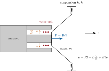
A coil of total wire length sits in a radial field so that every element of wire is perpendicular to ; it moves along its axis at speed and carries . Then it feels the axial Laplace force and is the seat of the back-emf (receiver convention: a voltage ). With a mass , a suspension of stiffness and a mechanical damping , fed by a voltage through the coil’s resistance and inductance :
Multiplying by and by and adding: the electrical power equals the Joule loss plus the growth of the stored energies plus the mechanical loss (which includes the sound): the conversion term cancels between the two equations. Run backward (motion imposed, read) the same device is a dynamic microphone.
Proof. Laplace force on each element , all axial and of the same sign; emf from summed over the wire. The energy balance is the sum of the two equations multiplied as stated. ∎
Remark 29.13 (Why the coupling damps)
At low frequency (), and the force is : the electrical circuit adds the damping to the mechanical one. A loudspeaker connected to an amplifier (low output resistance) is heavily damped — its cone stops when the signal stops — and the same coupling is what lets the microphone take energy from the sound (Problem 29.1).
29.5 Exercises
Exercise 29.1 ★
A coil of turns and in a uniform field at to its normal. Flux; mean emf if the field is switched off in ; in ; sense of the induced current relative to the field (Lenz).
Solution
Solution of Exercise 29.1.
; in , in . The current flows so as to recreate the vanishing flux: its field is along the old .
Exercise 29.2 ★
A bar long slides at on rails closed by , in . Emf, current, Laplace force, force the pusher must apply, mechanical power, electrical power.
Solution
Solution of Exercise 29.2.
; ; braking, so the pusher applies ; .
Exercise 29.3 ★
Solenoid of , length , section : inductance; energy at ; time constant with a resistance; field inside and energy density, to check .
Solution
Solution of Exercise 29.3.
; ; . , over : .
Exercise 29.4 ★
A transformer from to : turns ratio; primary turns for a -turn secondary; primary current when the secondary delivers . Why does it not work on a car battery?
Solution
Solution of Exercise 29.4.
; turns; . A steady current makes a steady flux: no , no secondary voltage — and the primary, a short, would burn.
Exercise 29.5 ★★
Lenz’s law: give the sense of the induced current and the direction of the force in each case — (a) a north pole approaches a ring along its axis; (b) a ring lies in a field that grows; (c) a ring is dropped onto a magnet; (d) a magnet falls through a long copper tube. For (d), explain with energy why it falls at a small constant speed.
Solution
Solution of Exercise 29.5.
(a) The flux (along the approach) grows: the current makes a field opposing it — its own north pole faces the magnet’s north — and the ring is pushed away. (b) Current whose field opposes the growth; the ring, a dipole anti-aligned with , is pushed toward weaker field. (c) As it falls the flux grows: same current as (a), the ring is braked. (d) Each section of tube ahead of the magnet sees growing flux, behind it decreasing; both induced currents brake the magnet; at the speed where the Laplace force balances the weight, the magnet falls steadily and its lost potential energy becomes Joule heat in the tube.
Exercise 29.6 ★★
Alternator: , , , . Peak and rms emf; peak current and peak torque into ; mean electrical power; compare with the mean mechanical power, and with the instantaneous torque at the moment the emf vanishes.
Exercise 29.7 ★★
Magnetic brake. A square loop of side and resistance , mass , leaves a region of uniform field at speed (one side still in the field). Emf, current, braking force; equation of motion and time constant; distance travelled before stopping from ; where did the kinetic energy go?
Solution
Solution of Exercise 29.7.
, , (N). : , ; distance (if the field region is long enough). The kinetic energy, , is dissipated as in the loop.
Exercise 29.8 ★★
A small coil ( turns, section ) sits inside a long solenoid (), axes aligned. Mutual inductance; emf in the coil when the solenoid current ramps at , and when it is at . Does depend on which coil carries the current?
Solution
Solution of Exercise 29.8.
Flux of the solenoid’s field through the turns: . Ramp: ; at , : . is symmetric: the same number gives the flux the small coil sends through the solenoid — far harder to compute directly.
Exercise 29.9 ★★
Energy in a field: over , as in an MRI magnet. Energy; inductance for ; height to which that energy would lift a car of ; volume of liquid helium it boils in a quench ( per litre). Energy of the Earth’s field () in a room.
Solution
Solution of Exercise 29.9.
; ; ; helium: . Earth’s field: , in the room.
Exercise 29.10 ★★★
Rails as a motor. The bar of Exercise 29.2 (mass , no friction) is connected to a source through the resistance . (a) Electrical and mechanical equations; show . (b) Terminal speed and time constant. (c) Power balance: source power Joule mechanical; efficiency as a function of . (d) Numbers: , , the rest as in Exercise 29.2. (e) A rail gun accelerates a projectile with over in : exit speed (order of magnitude).
Solution
Solution of Exercise 29.10.
(a) (the back-emf opposes the source), : . (b) , . (c) Multiply the electrical equation by : , and is the mechanical power; efficiency — only at no load, where nothing is delivered. (d) , . (e) (taking ), , — ten kilometres per second, the promise and the problem of rail guns (the rails erode).
Exercise 29.11 ★★★
Faraday’s disk. A copper disk of radius rotates at about its axis in a uniform along the axis; brushes touch the centre and the rim. (a) Emf between centre and rim by summing along a radius: . (b) Numbers: , , . (c) Why is it a low-voltage, high-current machine; current into , and the braking torque. (d) Recover from Faraday’s law applied to the circuit brush–radius–rim–brush: which flux varies?
Solution
Solution of Exercise 29.11.
(a) At radius the metal moves at ; is radial, of magnitude : . (b) : . (c) One “turn” only, so volts at most; into : , torque . (d) The circuit brush–radius– rim–brush sweeps out area per : — the flux through the moving, deforming circuit.
Exercise 29.12 ★★★
Induction cooktop. The coil under the glass carries with at ; the pan bottom acts as a single turn of resistance coupled by (inductance of the pan turn neglected). (a) Emf induced in the pan, peak value. (b) Current and mean power dissipated in the pan. (c) Why a high frequency, and why does the heat appear in the pan and not in the glass? (d) The pan’s current reacts on the coil: emf it induces there (peak), and the extra power the generator must supply — check it equals (b).
Solution
Solution of Exercise 29.12.
(a) , peak . (b) peak; . (c) The emf is : high frequency gives a useful emf with a modest ; the glass is an insulator, nothing flows in it — the heat is born inside the metal. (d) The pan current induces in the coil peak, in phase with (the pan current lags by nothing, being resistive, and lags by … so the reflected emf is , in phase opposition to ’s driving voltage): the generator supplies more — exactly what the pan dissipates.

29.6 Problem: The bicycle dynamo and the loudspeaker
Problem 29.1
Weekend problem — two electromechanical converters taken apart: a dynamo that regulates itself, and a loudspeaker whose amplifier is also its brake
Part I — The bicycle dynamo. A coil of turns and area turns in a uniform field ; its axle carries a roller of radius pressed against the tyre, so that the coil turns at for a bicycle speed . Coil resistance , inductance ; the lamp is a resistance .
- Flux through the coil and induced emf as functions of time; amplitude and frequency at .
- Neglecting first: rms current and power in the lamp at ; is a “, ” lamp comfortable?
- Mean mechanical power the cyclist supplies to the dynamo, and the corresponding force on the tyre (compare with rolling friction, about ).
- Explain with Lenz’s law why the dynamo resists, and why a lamp that lights “for free” does not contradict energy conservation.
- Now include : complex impedance of the circuit; show that the current amplitude is and that it saturates at high speed; its limit, and the speed at which it reaches of the limit.
- Without the inductance, what would the lamp receive at downhill? With it?
- Current and lamp power at and at ; comment on the self-regulation.
- Real dynamos rotate a magnet inside a fixed coil. Does the analysis change? What practical problem does it remove?
- What does the lamp do when the bicycle stops at a red light, and how do modern lights fix it?
Part II — The loudspeaker. Voice coil: wire length in a radial field , resistance , inductance ; moving mass (coil and cone) ; suspension stiffness , mechanical damping . Sinusoidal regime, complex amplitudes.
- Force on the coil for a current ; back-emf for a speed (derive both, with signs).
- Write the electrical and the mechanical equations.
- Eliminate and show that .
- At frequencies where , show that the coupling acts as an extra mechanical damping ; value; resonance frequency of the cone and its quality factor with and without the electrical damping.
- The amplifier delivers of amplitude at : force, acceleration, displacement and velocity amplitudes of the cone (mass-controlled regime); back-emf amplitude compared with .
- Same current at the resonance frequency: velocity amplitude (damping-controlled) and back-emf; comment.
- Electrical power at ; mechanical power dissipated in (taken as the sound and suspension losses); efficiency.
- Why is the sound pressure proportional to the cone’s acceleration (admit it) the reason a mass-controlled cone gives a flat response above resonance?
- Why must the field be radial, and why is a tweeter small?
- Sketch the modulus of the impedance seen by the amplifier from to : value at low frequency, at resonance (use the damping-controlled velocity), and at .
Part III — Backward, and the books.
- The same device as a microphone: a sound moves the cone at ; open-circuit voltage.
- Loaded by : current, and the braking force on the cone; show that the microphone takes power from the sound through an effective damping .
- The coil is wound on an aluminium cylinder (the former), a closed turn of length and resistance : damping it adds; why formers are slit.
- Tap the cone of a loudspeaker whose terminals are left open, then of one whose terminals are shorted: which one rings longer, and why?
- Write the energy balance of the loudspeaker over one period at steady state, naming every term.
- Sum up: for each device, the law used and the two numbers worth remembering.
Solution
Solution of Problem 29.1.
1. , ; ; : amplitude , frequency .
2. ; lamp under : a , lamp is over-driven and will not last.
3. Mechanical electrical: ; — half the rolling friction; the cyclist feels it.
4. The induced current’s Laplace couple opposes the rotation (Lenz); the lamp’s energy comes from the cyclist’s legs, of it.
5. ; ; for , . : , , .
6. Without : , , in the lamp — it blows. With : peak, : hot, but ten times less.
7. : , , , : dim. : , , , . Four times the speed, times the current: the inductance regulates.
8. Only the relative motion matters: the flux through the fixed coil varies identically, same emf. No sliding contacts (brushes) are needed to bring the current out of a rotating coil.
9. No motion, no flux change, no light — hence the capacitor or small battery (“standlight”) charged while riding.
10. Each element of wire is perpendicular to the radial : , axial. Moving at , each element sees along the wire: , opposing the current that produces the motion (receiver convention: a voltage ).
11. ; .
12. ; ; substitute and solve for .
13. gives : extra damping . ; : open, with the amplifier.
14. , , , ; against : .
15. With the current imposed, (an amplitude of — a big excursion for ); , three times : the amplifier must supply to push at resonance — the impedance peak. A voltage-source amplifier would instead let the electrical damping hold the cone.
16. ; : efficiency — loudspeakers are heaters that whisper.
17. Above resonance is independent of frequency for a given current, so the pressure, , is flat: the mass-controlled band is the working band.
18. Radial field: the force is axial and the same at every position of the coil in the gap. A tweeter must stay mass-controlled to with a tiny excursion: light coil and cone; and a small cone radiates high frequencies in all directions.
19. Low frequency: small, ; at : with : ; at : . A peak at resonance, a flat floor, a rise with .
20. .
21. ; , opposing : , a damping of ; the power is taken from the sound and ends in the two resistors.
22. Former: , ten times : it would deaden the cone and waste power as heat; a slit breaks the closed turn.
23. Open: only damps, , it rings. Shorted: the back-emf drives a current through , damping is added, : it stops at once. (Try it.)
24. Over a period, stored energies return to their values: — electrical input Joule heat in the coil mechanical losses (sound radiated and suspension friction); the coupling term appears in both equations with opposite signs and cancels.
25. Dynamo: Faraday on a rotating coil — at , current capped at by its own inductance. Loudspeaker: Laplace force and back-emf — of electrical damping, efficiency. Microphone: the same coil backward — per millimetre per second.