书籍暂未推出简体中文版——当前显示英文版。
University Earth and Space Sciences — Year 1 · 本科一年级
17Faults, Folds and Fabrics
A road cutting shows a rock face polished like glass and scored with fine parallel grooves. Across the valley, a sea cliff shows beds of sandstone and shale bent into zigzags with straight sides and sharp corners. On a roof nearby, slates split into sheets a few millimetres thick, along planes that cross the layers of the mud they were made from. Each is a record of the deformation of rock, read at a different scale: the grooves give the direction in which two blocks slid past each other along a fault; the zigzags measure how much the beds were shortened; the slaty planes grew across the grain of the rock as it was squeezed. This chapter gives the geometry needed to measure the three records, and the mechanics of the previous chapter explains why faults take the dips they do.
You already know
The attitude of a plane is its dip direction and dip, written for instance ; its strike follows by the right-hand rule, the plane dipping to the right of an observer looking along the strike (Chapter 4). A fold is a bend of once-planar layers; an anticline is convex upward with the oldest rocks in its core, a syncline concave upward; the fold axis is the line along which the layers bend most (Chapter 4). The throw and heave of a fault are the vertical and horizontal components of its displacement (Chapter 5). A line has a trend and a plunge, and the downward unit vector (Chapter 6). A rock obeying the Coulomb criterion breaks on planes at from , and existing faults slip according to Byerlee’s law (Chapter 16). A mineral is in extinction between crossed polars when its vibration directions are parallel to those of the polars (Chapter 8). Faults were met in Book 1, grade 7; reverse faults, thrusts and foliation in Book 2, grade 12. The cross product of two vectors is perpendicular to both (mathematics, Year 1).
17.1 Faults: geometry and kinematics
A fault is a surface across which two blocks of rock have moved past each other. To describe the movement we need names for the two blocks and for the displacement, and a way to measure its direction within the plane of the fault.
Definition 17.1 (Hanging wall, footwall, slip vector, net slip, rake)
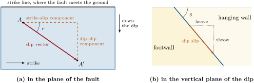
Let a fault be locally a plane that is not vertical. The hanging wall is the block above it, the footwall the block below it. Let be a point of the footwall and the point of the hanging wall that was in contact with it before the movement. The slip vector is the displacement of the hanging wall relative to the footwall; its length is the net slip. The rake (also called the pitch) of the slip vector is the angle, measured in the plane of the fault, from the strike direction given by the right-hand rule to the slip vector, positive when the slip vector points up the plane and negative when it points down it: . This is the seismologists’ convention, used again for earthquakes in Chapter 18; many field geologists record instead an angle between 0 and , measured clockwise from the strike seen from above, and add the sense of movement in words.
The two names come from mining: a miner working a sloping vein stood on the footwall and had the hanging wall over his head. A displacement seen in a single cut is not, in general, the slip: a bed offset on a map or in a section shows a separation, which depends on the attitude of the bed. The slip needs two points that were once one, such as the two halves of a line cut by the fault, for instance the edge of a dyke against a bed.
Proposition 17.2 (Components of the slip)
Let a fault have dip direction and dip , and a slip vector of length and rake . With east, north and up components, let be the unit vector along the strike and the unit vector up the dip. Then
its strike-slip component is and its dip-slip component ; the throw is , the heave , and the slip vector plunges by with .
Proof. The vector is horizontal and points along the strike; is the opposite of the downward unit vector of the dip line, which has trend and plunge (Chapter 6). Both lie in the fault plane, and , so they form an orthonormal basis of the plane. A vector of the plane of length at the angle from , counted toward , is . Its vertical component is , whose size is the throw; its horizontal part across the strike is times the horizontal part of , of length , which is the heave; and the sine of its plunge is its vertical component divided by . ∎
For a dip-slip fault, and the heave is the throw divided by , as in Chapter 5. The rake sorts faults into families.
Definition 17.3 (Normal, reverse, thrust, strike-slip and oblique-slip faults)
A fault whose slip vector lies along the dip line () is a dip-slip fault: a normal fault when the hanging wall has moved down (), a reverse fault when it has moved up (). A thrust fault is a reverse fault that dips or less. A fault whose slip is parallel to its strike ( or ) is a strike-slip fault; such faults are usually near vertical. A strike-slip fault is dextral (right-lateral) when an observer standing on one side sees the other side moved to the right, sinistral (left-lateral) when to the left. A fault whose slip has both a strike-slip and a dip-slip component is an oblique-slip fault; in practice a fault is named after its larger component, so that a rake near is called normal.
Proposition 17.4 (The sense of a strike-slip fault)
The sense of a strike-slip fault does not depend on the side the observer stands on. A rake near is sinistral, a rake near dextral.
Proof. If an observer on block 1 sees block 2 move by , an observer on block 2 sees block 1 move by . Turning round to face block 1, the second observer has exchanged left and right. The two changes cancel: both see the other side go the same way, to the right or to the left. For the second part, stand on the footwall and face the hanging wall: one then looks down the dip direction, and since the plane dips to the right of its strike, the strike direction points to one’s left. A rake of moves the hanging wall along the strike, to the left; a rake of moves it to the right. ∎
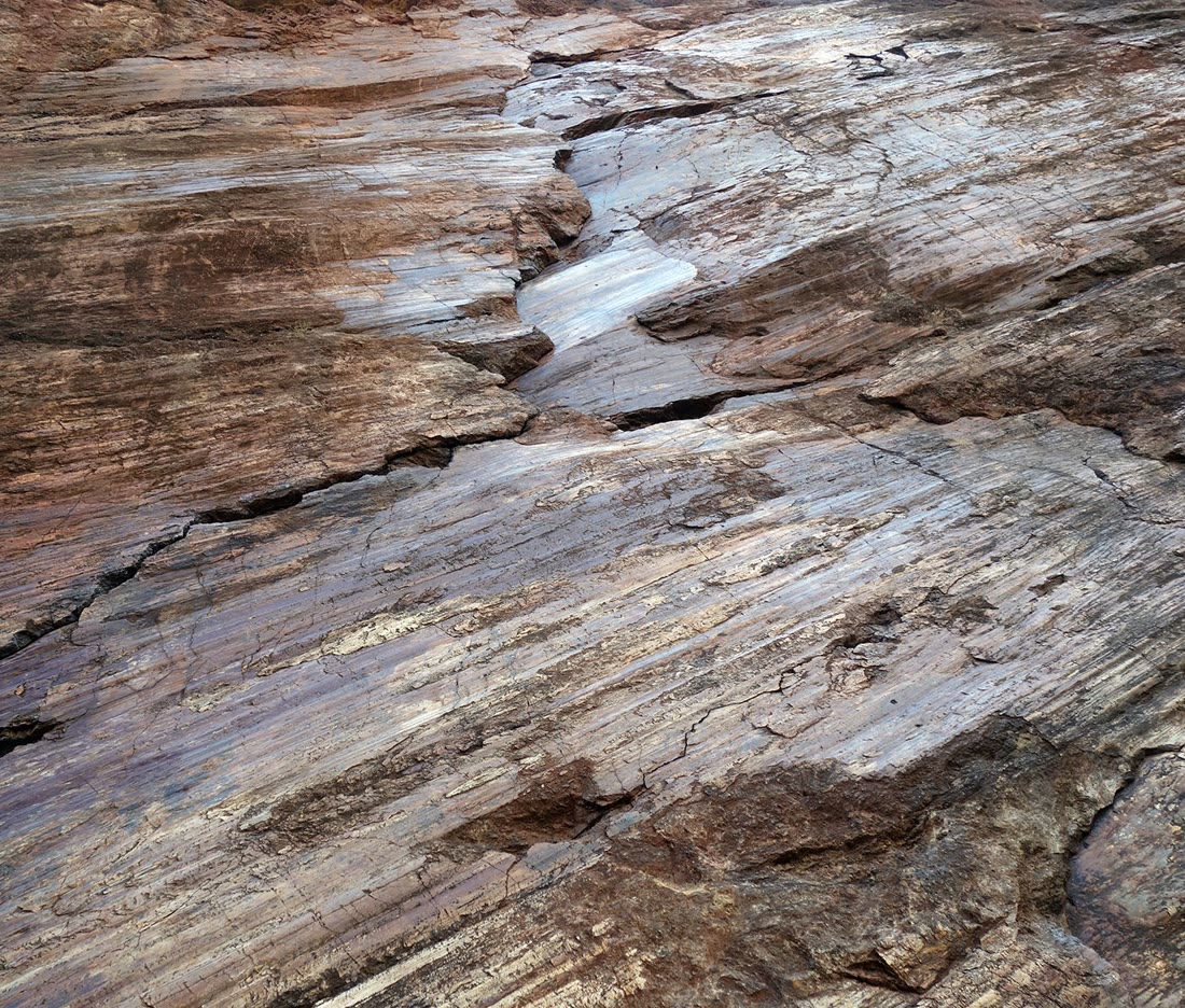
A fault surface is often itself a record of the movement: the scratches and fibres on it lie along the slip. Around the surface, a fault zone may be filled with rock broken by the movement.
Definition 17.5 (Slickenside, slickenlines, fault rocks)
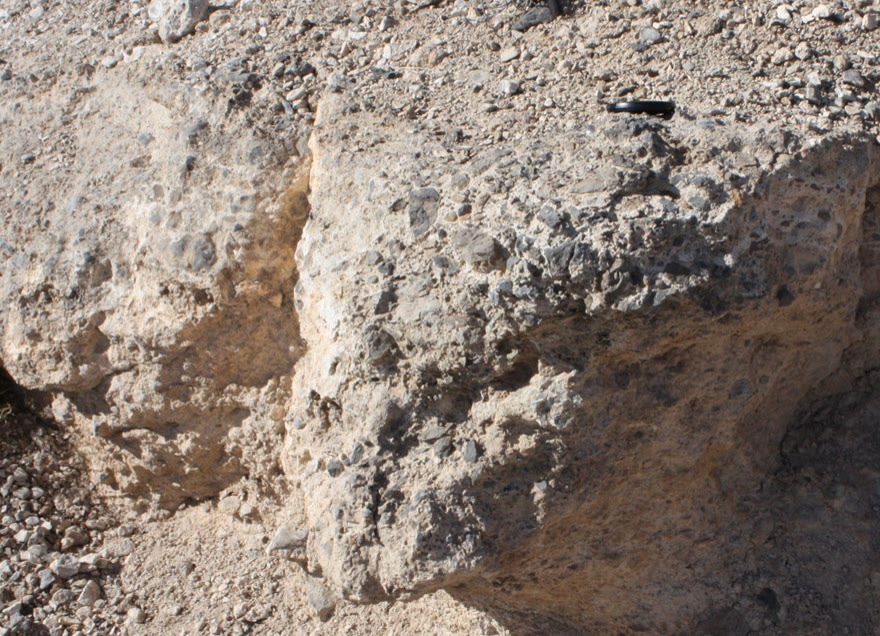
Slickenlines are scratches or fibres on a fault surface, parallel to the slip; a slickenside is a fault surface that carries them, often smoothed by the slip. A fault rock is a rock made by the movement on a fault. A fault breccia is made of angular fragments of the walls of the fault, rotated and moved out of place, from huge blocks down to about ; a cataclasite is made of fragments of sand size or smaller; neither has a fabric, the fragments lying at random. A fault gouge is a fault rock rich in clay, very soft in outcrop. A mylonite is a fine-grained, strongly foliated rock made in a shear zone by ductile shearing, the grains shrunk by recrystallisation rather than by milling.
The fault rocks are a depth gauge, and they follow the strength envelope of Chapter 16. Gouge, breccia and cataclasite, with their random fabric, are made by frictional sliding and fracture in the brittle crust; mylonites are made below the brittle–ductile transition, where the fault continues downward as a band of ductile shear. For a normal geotherm and enough water, the transition between the two lies at , close to the of the envelope of the previous chapter, and the fault is strongest there. Across a large fault brought up from depth, the same order is found side by side: gouge zones near the surface, then cataclasite, then mylonite. The name mylonite, from the Greek word for milling flour, records a mistake: it was thought to be ground rock. The Year 3 volume studies those deep shear zones and the mechanisms that make mylonites.
Method 17.6 (Measuring the slip on a fault)
- Measure the attitude of the fault surface and write its strike, .
- Measure the slickenlines: their rake on the fault, or their trend and plunge; for a rake , .
- Find which way the hanging wall moved, from markers offset across the fault, and give the rake its sign: negative if the hanging wall went down.
- Find the net slip from two points that were once one; if only the throw of a horizontal marker is known, .
- Compute the components with Proposition 17.2 and name the fault with Definition 17.3.
In the field — Measuring a fault surface
A geologist who finds a fault surface in an outcrop measures it like any other plane, with a compass-clinometer laid on the surface, and then measures the slickenlines on it, either as a rake, with a protractor laid on the plane, or as a trend and plunge. The two are checked against each other with the formula of step 2 of the method. The sense of movement is the hard part. Small steps on a slickenside, and fibres of quartz or calcite that grew as the blocks moved apart, can show which way the missing block went, but some steps point the wrong way, so the sense is trusted only when it agrees with the offset of a marker bed or a vein. Fault rocks are described and sampled, and a fault zone too broad to measure in one place is mapped as a band. Each fault is recorded at a numbered station of the notebook, with its attitude, its slickenlines, the sense of movement and how sure the geologist is of it.
17.2 Anderson’s theory of faulting
Why are most normal faults steep and most thrusts gentle? In 1905 the Scottish geologist Ernest Masson Anderson answered with two remarks: the surface of the Earth fixes the directions of the principal stresses, and the Coulomb criterion then fixes the angle of the faults.
Proposition 17.7 (A free surface makes a principal plane)
At the surface of the Earth, where it is horizontal, one principal stress is vertical and the other two are horizontal.
Proof. The air presses on the ground only with its pressure, normal to the surface: it exerts no shear stress. The stress on the horizontal plane at the surface is therefore normal to it. In three dimensions, the stress on a plane of unit normal is the vector (physics books, Year 3); if it has no shear part, it is parallel to , so that and is an eigenvector of the symmetric matrix : a principal direction (Definition 16.4). The vertical is thus a principal direction, and the two others, perpendicular to it, are horizontal. ∎
Anderson assumed that the principal stresses keep these directions down to the depths at which faults form. The assumption holds well under a gently sloping surface and in rocks without strong old weaknesses; it fails near steep relief and where old faults or layers guide the new ones. With it, only three cases are possible, according to which of , and is vertical.
Theorem 17.8 (Anderson’s theory of faulting)
Let one principal stress be vertical and let the rock break according to the Coulomb criterion, with angle of internal friction . New faults form on planes that contain the direction of and make the angle with , and they slip perpendicular to , shortening the rock along . Hence
- if is vertical, normal faults form, striking along and dipping ;
- if is vertical, thrust faults form, striking along and dipping ;
- if is vertical, vertical strike-slip faults form, striking at on either side of .
With , the dips are , and .
Proof. On a plane that contains the direction of , the normal lies in the plane of and , and the stress on the plane is that of the two-dimensional problem of Chapter 16: its point lies on the Mohr circle of and , and its shear part lies in the plane of and , perpendicular to . On any other plane, the point lies inside that circle, which is the largest of the three Mohr circles of a three-dimensional state of stress (admitted from the three-dimensional theory). As the stresses grow, the Coulomb line is therefore first touched by planes containing , and among them, by Theorem 16.14, by those at from . Slip on such a plane, perpendicular to , brings closer the two blocks along the direction of greatest compression and moves them apart along the least, as it must to relieve the stress. In case (a) the plane makes the angle with the vertical, so it dips ; it strikes along the horizontal ; the slip lies in the vertical plane of the dip, and the block above goes down, lengthening the rock horizontally: a normal fault. In case (b) the plane makes with the horizontal , and the slip shortens the rock horizontally, pushing the hanging wall up: a thrust fault. In case (c) the planes contain the vertical, so they are vertical; the slip is horizontal, perpendicular to : strike-slip faults, at on either side of the horizontal . ∎
In each regime two sets of faults are possible, symmetric about : conjugate faults, meeting at , about , with in the acute angle between them. Conversely, a pair of conjugate faults measured in the field gives the directions of the stresses that made them: bisects their acute angle, is their line of intersection.
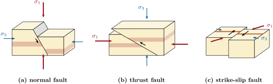
The three regimes match the three kinds of plate boundary of Chapters 13 and 14. Where the lithosphere is stretched, at rifts and ridges, the horizontal stress falls below the vertical one and normal faults form; where it is squeezed, at convergent margins and in mountain belts, the horizontal stress exceeds the weight of the rock and thrusts form; along transform faults the two horizontal stresses straddle the vertical one. The dips fit the observations in a rough way: the normal faults of rifts dip around near the surface, and thrusts are low-angle reverse faults. The exceptions are informative. Many normal faults flatten with depth, and some cross-sections of rifts show them reaching a nearly flat zone of shear: these low-angle normal faults, or detachments, cut the crust at well under . Anderson’s theory cannot explain them as new faults, and Exercise 17.10 shows that Byerlee’s friction cannot make them slip under Andersonian stresses either: they need weak fault rocks, high pore pressure or rotated stresses. A fault that already exists slips at the friction of Byerlee’s law, , ; the best-oriented normal faults then dip , as the problem of Chapter 16 found.
History — Anderson’s faults
Ernest Masson Anderson, a Scottish geologist, published his theory of the three kinds of faults in 1905, in a short paper on the dynamics of faulting, and gave its full form, with its application to the dykes and faults of Britain, in his book The Dynamics of Faulting and Dyke Formation. A small number of papers and that book still shape structural geology, seismology and rock mechanics: his three regimes, normal, thrust and strike-slip, are the usual way of sorting states of stress in the crust and the faults they make, and of reading the stress from the faults.
17.3 Fold geometry
Chapter 4 named folds and read their patterns on maps. In three dimensions a fold needs more names: where it bends, how sharply, and how it is set in space.
Definition 17.9 (Hinge, hinge line, limb, axial plane, interlimb angle, cylindrical fold)
On a folded surface, the hinge is the zone of greatest curvature and the hinge line the line that joins its points of greatest curvature; the limbs are the less curved parts on either side. The axial surface of a fold is the surface that joins the hinge lines of its successive folded surfaces; when it is a plane, it is the axial plane. The interlimb angle is the angle between the two limbs, measured in the profile, the plane perpendicular to the hinge line, between the tangents to the limbs at their points of inflection; . A fold is a cylindrical fold when its surfaces are generated by a straight line moved parallel to itself; the direction of that line is the fold axis of Definition 4.14, and every hinge line of a cylindrical fold is a straight line parallel to it.
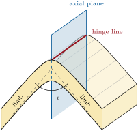
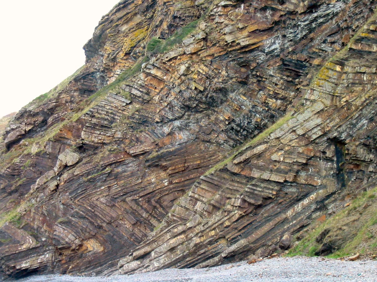
When the limbs are planes, as in the chevron folds below and in the Varden Hills, the geometry of a fold follows from the attitudes of its limbs. The upward unit normal of a plane of dip direction and dip is , in east, north and up components.
Proposition 17.10 (A fold from its limbs)
Let a cylindrical fold have planar limbs, neither overturned, with upward unit normals and . Its hinge line is parallel to , and its interlimb angle is
Proof. Each limb is generated by lines parallel to the fold axis, so it contains the direction of the axis, which is therefore perpendicular to both normals and parallel to their cross product; the hinge line is parallel to the axis. The profile is perpendicular to the axis, so it contains both normals; in it, the two limbs appear as two lines perpendicular to and , and the angle between the lines equals the angle between the normals or its supplement. When the layers are not folded the two normals coincide and the interlimb angle is ; as the limbs turn, the angle between the normals grows from while the interlimb angle decreases from , so that the two add up to as long as both normals point upward. ∎
For an upright fold whose two limbs dip on either side, the normals make the angle and .
Definition 17.11 (Classes of folds)
By its interlimb angle, a fold is a gentle fold ( from to ), an open fold ( to ), a tight fold ( to ) or, when its limbs are nearly parallel ( from to ), an isoclinal fold. By the dip of its axial plane, a fold is an upright fold when the axial plane dips more than , a recumbent fold when it dips less than , and an inclined fold in between. A fold one of whose limbs has turned past the vertical, so that both limbs dip the same way and the beds of that limb are upside down, is an overturned fold. A fold whose hinge line is not horizontal is a plunging fold.
Other limits are in use for the classes of tightness; this book keeps the four above.
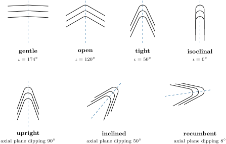
The thickness of the layers distinguishes two styles. In parallel, or concentric, folds each layer keeps its thickness measured perpendicular to it, as a stack of sheets of paper does when it is bent; such folds form by buckling of strong layers interbedded with very weak ones. In similar folds every surface has the same shape, the layers keep their thickness measured parallel to the axial plane, and they thin on the limbs and thicken in the hinges, as the profiles drawn above do; they form when all the layers are weak, so that they play no mechanical part. Chevron folds have straight limbs and narrow hinges, with an interlimb angle near ; they are parallel folds of strong layers set close together, which slide over each other as they bend.
17.4 Fabrics
A deformed rock is often deformed throughout, not only on a few surfaces: its grains are flattened, turned or regrown into a common orientation, which gives it a fabric. A planar fabric makes the rock split, a linear one makes it break into rods.
Definition 17.12 (Foliation, schistosity, slaty cleavage, axial-planar cleavage)
A foliation is a planar fabric that pervades a rock: a set of closely spaced parallel surfaces, made by aligned platy or flattened grains or by thin layers, along which the rock splits most easily. Schistosity is the foliation of a schist, made by aligned grains coarser than about . A cleavage is a foliation of a fine-grained rock made by its deformation; slaty cleavage is the cleavage of a slate, made by sheet silicates too small to be seen with the naked eye, and so closely set that the rock can be split almost anywhere into thin sheets. An axial-planar cleavage is a cleavage parallel, or nearly parallel, to the axial planes of the folds in the same rocks.
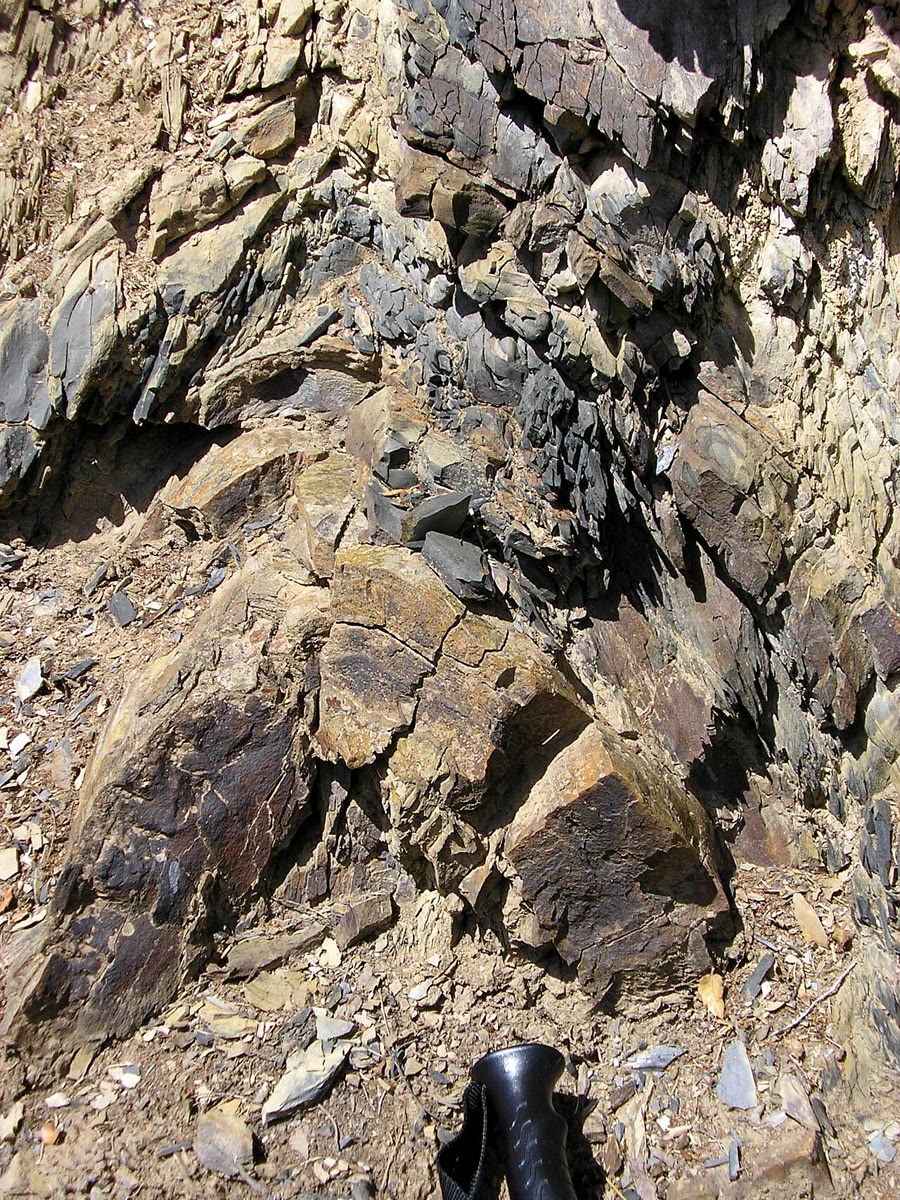
A foliation forms roughly perpendicular to the direction of greatest shortening, by the turning of platy grains, the growth of new micas, and the dissolution of grains on the faces that are pressed hardest. The cleavage of a slate therefore has nothing to do with the bedding of the mud: it records the squeezing. When folds and cleavage grow in the same shortening, the cleavage lies close to the axial planes of the folds, and it fans slightly across them, converging or diverging according to the strength of each layer, as the photograph below shows.
Definition 17.13 (Lineation, intersection lineation, stretching lineation)
A lineation is a linear fabric that pervades a rock, measured by its trend and plunge. An intersection lineation is the set of lines in which two planar fabrics cut each other, such as the bedding and a cleavage; a stretching lineation is made of grains or pebbles drawn out along the direction of greatest stretch.
Proposition 17.14 (The intersection lineation of a fold)
In a cylindrical fold with an axial-planar cleavage, the intersection lineation of the bedding and the cleavage is parallel to the hinge line, everywhere on the fold.
Proof. Every bedding surface of a cylindrical fold contains the direction of its axis. The axial plane contains the hinge lines, which are parallel to the axis, so it contains that direction too, and so does every cleavage plane parallel to it. Two planes that are not parallel and both contain the same direction meet along a line of that direction. ∎
The proposition is the field geologist’s way to the plunge of a fold too large to be seen whole: on any outcrop of either limb, the lines in which the cleavage cuts the bedding give the hinge line. The bedding and the cleavage together say more: where the fold is, and which way up the beds are.
Definition 17.15 (Vergence)
The vergence of an asymmetric fold is the horizontal direction toward which its upper part has moved relative to its lower part: the direction in which it is overturned or, for an inclined fold, toward which it leans.
Proposition 17.16 (Bedding and cleavage on the limbs of a fold)
Consider a fold with straight limbs and an axial-planar cleavage, in rocks that were the right way up before folding, and in which both limbs descend from each anticline hinge. Seen in the profile:
- on a limb where the bedding and the cleavage dip the same way, the bedding is the steeper of the two exactly when the limb is overturned;
- the acute rotation that turns the cleavage onto the bedding has opposite senses on the two limbs of a fold; on a limb that is not overturned, it moves the top of the cleavage horizontally toward the anticline hinge at the top of that limb.
Proof. Look along the hinge with the axial plane dipping to the left at the angle , , and count angles anticlockwise from the horizontal pointing right. The cleavage, parallel to the axial plane, runs upward at the angle . At an anticline hinge the two limbs leave downward at the angles (limb 1) and (limb 2), on either side of the axial plane, with since both descend; every limb of a train of folds is one of these two for the anticline at its top. The rocks young outward, away from the core of the anticline, along the normal to the limb that points away from the axial plane.
Limb 1 goes down to the left: it dips to the left at , less steeply than the cleavage. Its outward normal, at , points upward: it is the right way up. Running upward, it makes the angle , so the acute rotation from the cleavage to the bedding is clockwise, through : the top of the cleavage moves to the right, where the hinge is, since the limb leaves the hinge toward the left.
Limb 2 makes the angle with the horizontal, upward. If , it goes down to the right and dips to the right, opposite to the cleavage; its outward normal, at , has the upward component : it is the right way up. If , it goes down to the left, dipping to the left at , more steeply than the cleavage, and the same component is negative: the limb is overturned. In both cases the acute rotation from the cleavage to the bedding is anticlockwise, through , and moves the top of the cleavage to the left; when the limb is the right way up it leaves the hinge toward the right, so the hinge is to the left. Limbs that dip the same way as the cleavage are thus limb 1, less steep, and an overturned limb 2, steeper, which is (a); the senses are clockwise on limb 1 and anticlockwise on limb 2, which is (b). ∎
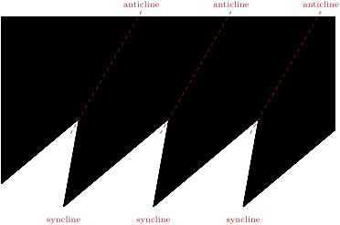
The sense of the rotation thus changes at every hinge, anticline or syncline. A geologist who records it along a traverse finds the hinges of folds too large to see in one outcrop where the sense changes, and the overturned limbs where the bedding is steeper than the cleavage; the word vergence is also used for this sense of rotation, and the reversals of minor-fold vergence are mapped in the same way to find the hinges of major folds: the small folds on the two limbs of a large one have opposite asymmetries, and its axial trace runs between them.
17.5 Microstructures
Under the microscope, the deformation of a rock shows in its grains. A grain of quartz bent by the slow gliding of its crystal lattice no longer goes into extinction all at once between crossed polars: as the stage turns, a dark band sweeps across it, because its parts point in slightly different directions. This undulose extinction (Chapter 8) grows stronger as a shear zone is approached, because defects pile up in the crystal lattice. Where water is present, grains dissolve on the faces where they are pressed hardest and the dissolved matter is deposited where the stress is lower, or carried away: this pressure solution shortens rocks at low temperature and builds many cleavages. At higher temperature, the strained grains are replaced, while the deformation goes on, by new, smaller and unstrained ones, first along the old grain boundaries: dynamic recrystallisation, which shrinks the grain size and makes mylonites. The shapes of deformed grains and of the minerals that grow in their shadows also show which way a shear zone moved; these shear-sense indicators, and the mechanisms themselves, belong to the Year 3 volume.
17.6 Exercises
Exercise 17.1 ★
Name each fault from the rake of its slip vector, the plane dipping : (a) ; (b) ; (c) ; (d) ; (e) . (f) What would (b) be called if its dip were ?
Solution
Solution of Exercise 17.1.
(a) A normal fault. (b) A reverse fault, nearly pure dip-slip. (c) A sinistral strike-slip fault. (d) A dextral strike-slip fault. (e) An oblique-slip fault: the hanging wall moved down and along the strike, to the left; its strike-slip component, of the net slip, is larger than its dip-slip component, , so it is called a sinistral fault with a normal component. (f) With a dip of , less than , the reverse fault is a thrust fault.
Exercise 17.2 ★
A normal fault dips ; its slip is pure dip-slip, with a net slip of . Compute its throw and its heave.
Exercise 17.3 ★
Give the interlimb angle and the class of each upright fold, whose limbs dip in opposite directions: (a) limbs dipping and ; (b) and ; (c) and .
Solution
Solution of Exercise 17.3.
For an upright fold whose limbs dip and in opposite directions, . (a) : open. (b) : tight. (c) : isoclinal.
Exercise 17.4 ★
A sandstone has the angle of internal friction . Following Anderson’s theory, at what angles do its normal faults and its thrust faults dip? What angle do two conjugate strike-slip faults make with each other?
Solution
Solution of Exercise 17.4.
Normal faults dip , thrusts . Conjugate strike-slip faults each make with , on either side of it, so they meet at .
Exercise 17.5 ★★
A fault has the attitude , and slickenlines of rake on it; the net slip is . (a) Compute the strike-slip and dip-slip components, the throw and the heave. (b) Write the slip vector in east, north and up components, and give its trend and plunge. (c) Name the fault.
Solution
Solution of Exercise 17.5.
(a) The strike-slip component is along the strike, the dip-slip component , that is down the dip; the throw is and the heave . (b) The strike is , so ; . Then in metres. Its trend is and its plunge , which is also . (c) An oblique-slip fault: the rake lies between and , closer to : a sinistral fault with a normal component.
Exercise 17.6 ★★
Two vertical strike-slip faults of the same age strike and . (a) Following Anderson, give the directions of , and , and the angle of internal friction of the rock. (b) Which fault is dextral and which sinistral? Argue from the shortening along .
Solution
Solution of Exercise 17.6.
(a) The two faults make with each other; bisects the acute angle, so it is horizontal along (and ); is horizontal along ; is vertical, along the line in which the two vertical faults meet. Each fault makes with , so and . (b) The two faults cut the ground into four wedges; the wedges that contain , toward and toward , move toward each other, and those that contain move apart, toward and . Take the fault striking , between the wedge toward (to its east) and the wedge toward (to its west): relative to the western wedge, the eastern one moves toward and away from , both of which have a component toward along the fault. An observer on the western wedge, facing east, sees the eastern one move toward , to the right: the fault striking is dextral. The same argument, or the symmetry about , makes the fault striking sinistral.
Exercise 17.7 ★★
The two limbs of a cylindrical fold have the attitudes and . With Proposition 17.10, find the trend and plunge of its hinge line, its interlimb angle and its class.
Solution
Solution of Exercise 17.7.
The upward normals are
Their cross product is , which points downward: the hinge line plunges toward . , the angle between the normals is , and : an open fold.
Exercise 17.8 ★★
At an outcrop, the bedding has the attitude and an axial-planar cleavage the attitude . Find the trend and plunge of the intersection lineation. What does it tell about the fold?
Solution
Solution of Exercise 17.8.
for the bedding and for the cleavage. Their cross product, taken downward, gives a line that plunges toward . By Proposition 17.14, this is the direction of the hinge line: the fold plunges about toward the east-north-east, which any other outcrop of either limb should confirm.
Exercise 17.9 ★★
A vertical fault strikes east–west. A vertical dyke striking north–south crosses it; north of the fault the dyke is found east of where it is south of the fault. (a) Is the fault dextral or sinistral? (b) If the slickenlines are horizontal, what is the net slip? (c) If instead they plunge to the east, what are the net slip and the vertical component of the slip, and which block went down?
Solution
Solution of Exercise 17.9.
(a) An observer south of the fault, facing north, sees the northern part of the dyke displaced to the east, to the right: the fault is dextral. (b) The dyke is a vertical plane perpendicular to the fault, so its offset along the strike is the strike-slip component: , which is the whole slip if the slickenlines are horizontal. (c) The slip then makes with the strike in the vertical fault plane: its horizontal component is still , so the net slip is and its vertical component . The northern block moved east, and the slickenlines descend toward the east, so it also went down, by . A vertical dyke cannot show that vertical movement, since sliding it along itself leaves its trace unchanged.
Exercise 17.10 ★★★
A fault with no cohesion and the friction coefficient makes the angle with . (a) Show that it slips when the effective principal stresses reach the ratio
(b) With and vertical, compute the ratio for normal faults dipping , and . (c) Show that a normal fault dipping less than a certain angle can never slip, and compute that angle. (d) For and , give the dips of the best-oriented normal and thrust faults.
Solution
Solution of Exercise 17.10.
(a) The normal to the fault makes with , so by Proposition 16.5, and . Slip starts when ; dividing by and writing , , so , which is the formula. (b) With vertical, is minus the dip: gives ; , ; , . (c) The denominator vanishes when , ; beyond it, would be negative: no ratio of positive effective stresses can make the fault slip, however large becomes. Normal faults dipping less than cannot slip under a vertical with . (d) The best-oriented plane is at from . For , : normal faults dip , thrusts . For , : and .
Exercise 17.11 ★★★
Along an east–west traverse across chevron folds whose hinges trend north, an axial-planar cleavage dips to the west everywhere. The bedding dips W at station A, W at station B and W at station C, from west to east, in rocks that were the right way up before folding. (a) Which station is on an overturned limb? (b) In which sense does the cleavage turn onto the bedding at each station, seen looking north? (c) Where are the hinges, and which are anticlines? (d) Find the interlimb angle and the attitude of the axial planes, and say which way the folds verge.
Solution
Solution of Exercise 17.11.
Looking north, east is to the right, and planes dipping west rise toward the right. (a) At B the bedding dips the same way as the cleavage, more steeply: by Proposition 17.16(a), B is on an overturned limb; A and C, where the bedding is less steep, are the right way up. (b) The cleavage rises at ; at A and C the bedding rises at , and the acute rotation from one to the other is clockwise, through , moving the top of the cleavage to the east; at B the bedding rises at and the rotation is anticlockwise, through , moving it to the west. (c) The sense changes between A and B and again between B and C: there is a hinge in each interval. At A, which is the right way up, the top of the cleavage moves east, toward the anticline at the top of the limb: the hinge between A and B is an anticline, and the one between B and C a syncline. (d) In the notation of the proof, the right-way-up limbs dip and the overturned limbs , so , as the cleavage says, and : tight folds. The axial planes strike north and dip to the west, attitude . The short limbs have turned past the vertical with their tops toward the east: the folds verge to the east, as in the figure of the chapter.
Exercise 17.12 ★★★
A layer of length is folded into a train of symmetric chevron folds of interlimb angle , with its length unchanged. (a) Show that its length measured across the folds becomes . (b) What shortening do chevron folds of interlimb angle represent? (c) What interlimb angle corresponds to a shortening of ? (d) A train of upright folds with limbs dipping : what shortening?
Solution
Solution of Exercise 17.12.
(a) In a symmetric chevron fold each limb makes the angle with the axial plane, which is perpendicular to the direction of shortening; a limb of length therefore spans across the folds, and the whole layer . (b) : a shortening of . (c) gives . (d) and : a shortening of , which is also .
17.7 Problem: The Varden Hills’ structures, measured
Problem 17.1
Weekend problem — the anticline and the normal fault of the Varden Hills, from the attitudes of their planes to the slip on the fault
The Varden Hills are folded into an anticline, whose axis runs north–south at , and a syncline to the east of it; both have planar limbs. A field survey measured the bedding on the east limb of the anticline as and on its west limb as . The cover is cut by a normal fault of attitude , whose hanging wall moved down the dip, with a throw of . Give angles to and lengths to .
Part I — The limbs.
- Write the upward unit normals (east limb) and (west limb) in east, north and up components.
- Compute and the angle between the normals.
- Deduce the interlimb angle of the anticline.
- Classify the anticline by its interlimb angle.
- The two limbs dip . Why is the interlimb angle not exactly ? Compute the apparent dip of either limb in an east–west vertical section.
- The syncline shares the east limb of the anticline, and its own east limb is parallel to the anticline’s west limb. What is its interlimb angle?
Part II — The hinge line and the axial plane.
- Compute , and the trend and plunge of the hinge line.
- Give the attitude of the axial plane. Is the anticline upright, inclined or recumbent?
- Give the full description of the fold: tightness, attitude of the axial plane, plunge.
- On the geological map of Chapter 4, which way do the outcrops of the anticline close, and what crops out in its core?
- The shale of the cover carries an axial-planar cleavage. Give its attitude, and the trend and plunge of its intersection lineation on the east limb.
- On the east limb, in which sense does the cleavage turn onto the bedding, seen looking north, and on which side is the anticline hinge?
Part III — The fault and the stresses.
- Give the strike of the fault by the right-hand rule, and say on which side of its trace the hanging wall lies.
- Which principal stress was vertical when the fault formed, according to Anderson?
- Give the directions of the two horizontal principal stresses.
- What angle of internal friction does the dip imply? What coefficient of internal friction?
- Give the attitude of the conjugate set of faults that the same stresses could have made, and the angle between the two sets.
- Would the fault be best oriented to slip again under the same regime, with Byerlee’s friction of 0.85?
Part IV — The slip.
- Give the rake of the slip vector, and its trend and plunge.
- Write the unit vector of the slip in east, north and up components.
- Compute the heave of the fault.
- Compute the east and north components of the horizontal displacement of the hanging wall.
- Check that the net slip , the throw and the heave satisfy , and explain why.
- To the nearest metre, what is the net slip on the Varden fault?
Solution
Solution of Problem 17.1.
1. gives
2. , and the angle between the normals is .
3. By Proposition 17.10, .
4. Between and : an open fold.
5. The limbs dip toward and , not due east and west, because the fold plunges: their steepest lines are not in the profile, which shows only an apparent dip. In an east–west section, by Theorem 5.4, , so , and (the profile is tilted from that section, which changes nothing to this precision).
6. Its limbs are parallel to those of the anticline, so its interlimb angle is also .
7. . Taken downward, : the hinge line trends and plunges to the north.
8. The axial plane contains the hinge line and bisects the two limbs; its normal is along , horizontal and east–west. It is vertical and strikes north–south: . The anticline is upright.
9. An open, upright fold, plunging to the north.
10. By Proposition 4.15, the outcrops of an anticline close in the direction of plunge: to the north. Its core holds the oldest rocks: the sandstone at the base of the cover and, where the river has cut deepest, the basement of schist and granite beneath it.
11. Axial-planar, the cleavage is vertical and strikes north–south, . By Proposition 17.14, its intersection lineation with the bedding is parallel to the hinge line: trend , plunge . Directly: the plane meets the vertical plane striking north along a line of plunge toward .
12. Looking north, the east limb rises toward the left at and the cleavage is vertical: the acute rotation from the cleavage to the bedding, through , is anticlockwise and moves the top of the cleavage to the west. The limb is the right way up, so by Proposition 17.16(b) the anticline hinge is to the west, at , as the map shows.
13. The strike is ; the plane dips toward , so the hanging wall lies on the east-south-east side of the trace.
14. The fault is normal: was vertical.
15. is horizontal along the strike, –; horizontal across it, –.
16. gives , and .
17. The conjugate set strikes as well and dips the other way: . The two sets meet at , with the vertical bisecting the acute angle.
18. With , and the best-oriented normal faults dip ; the Varden fault, at , is off. By Exercise 17.10, it slips at the ratio , against for the best plane: it is nearly, but not exactly, the best oriented, and would slip again at a stress ratio only higher.
19. The slip is down the dip: ; the slip vector trends and plunges .
20. .
21. .
22. East: ; north: , that is to the south.
23. , and . The throw and the heave are the vertical and horizontal components of the slip, which lies in the vertical plane of the dip: they are the sides of a right triangle whose hypotenuse is the slip.
24. To the nearest metre, the net slip on the Varden fault is .
本章定义的术语
- Classes of folds
- Foliation, schistosity, slaty cleavage, axial-planar cleavage
- Hanging wall, footwall, slip vector, net slip, rake
- Hinge, hinge line, limb, axial plane, interlimb angle, cylindrical fold
- Lineation, intersection lineation, stretching lineation
- Normal, reverse, thrust, strike-slip and oblique-slip faults
- Slickenside, slickenlines, fault rocks
- Vergence