University Physics — Year 2 · Bachelor Year 2
15Reflection and Transmission at Interfaces
The sonographer squeezes a gel between the probe and the skin: without it the sound would bounce off the film of air and never enter the body. A camera lens is coated with a film a quarter of a wavelength thick, and its surfaces stop reflecting. A radio wave meets the ionosphere and turns back; light meets a silver mirror and turns back; a pulse reaches the end of a cable and comes back inverted or upright according to what is connected there. Every wave, meeting a change of medium, splits into a reflected and a transmitted part, and one idea decides the shares: the continuity conditions at the interface, written with the impedances of the two media. This chapter applies it to sound, to light between two dielectrics, to a plasma, to a metal, and to a cable, and draws from it the laws of reflection and refraction and the one angle at which glass reflects nothing.
15.1 Normal incidence: the impedance rule
Theorem 15.1 (Reflection and transmission at normal incidence)
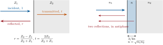
A plane wave travels in medium 1 toward the plane interface with medium 2; each medium is characterized by an impedance (the ratio of the two field quantities continuous at the interface — pressure and velocity for sound, and for light, voltage and current for a line). Continuity of both quantities at gives, for the "force-like" quantity (pressure, , ),
(For the "flow-like" quantity — velocity, , current — changes sign.) Nothing is reflected when (matched media); almost everything when () or ().
Proof. Incident , reflected , transmitted , same frequency. The associated flow quantities are , (a wave going backward carries ) and . Continuity at : and ; solve. Energies: the intensities are , so and . ∎
Example 15.2 (Sound at three interfaces)
Air () to water (): , — reflected; a swimmer hears almost nothing of the world above, and the ultrasound probe needs its gel. Tissue () to bone (): , . Fat () to muscle (): , — the faint echoes an image is made of. A string tied to a wall (): for the force, for the velocity, the pulse returns inverted (Chapter 6).
Proposition 15.3 (Light at normal incidence; anti-reflection coating)
For light between two transparent media of indices , (the impedance of a dielectric is , inversely proportional to ), for the electric field
at each air–glass surface, for water, for diamond. A layer of index and thickness between the media cancels the reflection at (quarter-wave anti-reflection coating): the waves reflected at its two faces have equal amplitudes and opposite phases. The same layer with a high index, or a stack of alternating quarter-wave layers, does the opposite and builds a mirror that reflects — the mirrors of lasers.
Proof. Continuity of the tangential and (no surface current): and with in each medium, i.e. the impedance rule with . Coating: the two reflected amplitudes are and , equal when ; a round trip in the layer adds the phase , so they cancel (multiple reflections, small, included in the exact treatment of Exercise 15.5). ∎
15.2 Oblique incidence: the laws of Descartes and the Brewster angle
Theorem 15.4 (Laws of reflection and refraction)
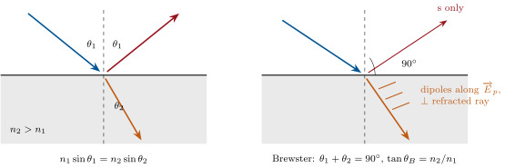
A plane wave of wavevector meets the plane interface between two media in which waves travel at and . The continuity conditions must hold at every point of the interface and every time: the reflected and transmitted waves must have the same frequency and the same tangential wavevector as the incident one. Hence the three wavevectors are coplanar (the plane of incidence), the angle of reflection equals the angle of incidence, and
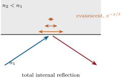
When and no real exists: total internal reflection; the field in medium 2 is then an evanescent wave, travelling along the interface and decaying away from it over , a fraction of a wavelength; it carries no energy away — total reflection.
Proof. With and the interface , the phases of the three waves must agree for all , : same , same . If , is imaginary, : evanescence; its Poynting vector along averages to zero. ∎
Proposition 15.5 (Brewster’s angle; polarization by reflection)
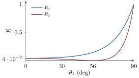
For light falling on a dielectric, the reflected amplitude depends on the polarization (Fresnel’s coefficients, admitted in general): for the polarization in the plane of incidence (p) it vanishes at the Brewster angle
at which the reflected and refracted rays are perpendicular; light reflected at is then completely polarized perpendicular to the plane of incidence (s), and partially so around it — the glare on water and roads that polarizing sunglasses remove. For glass () , for water .
Proof. The reflected wave is radiated by the dipoles of medium 2, set oscillating by the refracted wave along its , which for p polarization lies in the plane of incidence, perpendicular to the refracted ray. A dipole does not radiate along its own axis (Chapter 17); when the reflected direction is parallel to that axis — i.e. perpendicular to the refracted ray, — nothing is reflected. Then and Descartes gives . The s polarization has its perpendicular to the plane of incidence, never along the reflected ray: it is always partly reflected. ∎
15.3 Plasmas, metals and the perfect conductor
Proposition 15.6 (Reflection on a plasma and on a metal)
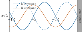
(i) A wave of at normal incidence on a plasma is totally reflected: the "index" is imaginary, has modulus , and the field penetrates as the evanescent of Chapter 14. (ii) A good conductor has , of huge modulus: , the reflectance is (Hagen–Rubens): for copper at , in the far infrared. (iii) The perfect conductor (, ): exactly for , the total tangential vanishes at the surface, the incident and reflected waves form the standing wave
with nodes of (antinodes of ) at ; the field is carried by a surface current , and the Laplace force on it is the radiation pressure .
Proof. (i) and (ii): the impedance rule with and the complex indices of Chapter 14; for (ii), and . (iii) With inside, the boundary relation gives , so ; sum the incident and reflected ; from Faraday; the jump of at the surface is ; the mean force per unit area on the sheet is (Chapter 12). ∎
Example 15.7 (Mirrors, radar, microwave ovens)
A metal mirror reflects by this mechanism: the incoming field drives a current in a skin a few nanometres deep ( for silver at ), which re-radiates the reflected wave; the missing heats the metal — which is why a high-power laser mirror is cooled, and why Chapter 14’s oven wall takes of the power. A radar sees an aircraft by the wave its skin re-radiates; a stealth aircraft replaces flat metal by absorbers and by shapes that reflect away from the radar. The nodes of the standing wave, apart in an oven, are the cold spots.
15.4 The end of a cable
Proposition 15.8 (Termination of a transmission line)
A line of characteristic impedance ends at in a load of impedance : the voltage wave is reflected with — nothing for a matched load , for a short circuit, for an open end. A mismatched line carries a partial standing wave whose ratio of maximum to minimum voltage is the standing wave ratio . Sending a short pulse and timing the echo locates a fault (time-domain reflectometry) and reads its nature from the echo’s sign.
Proof. At the load, with and (Chapter 8); the impedance rule once more. Standing-wave ratio: varies between and along the line. ∎
Method 15.9 (Any interface)
(1) Identify the two quantities continuous across the interface and the impedance of each medium as their ratio in a progressive wave. (2) Write incident reflected on one side, transmitted on the other, with equal frequencies and equal tangential wavevectors (Descartes). (3) Impose continuity: two equations, two unknowns , . (4) Energy: , for lossless media. (5) Check the limits: equal impedances (no reflection), infinite or zero impedance (, sign of ), and for layers, the phases of the successive reflections.
15.5 Exercises
Exercise 15.1 ★
Acoustic impedances: air , water , steel , soft tissue , bone . Reflection coefficients (pressure) and fractions of energy reflected for air–water, water–steel, tissue–bone, tissue–air. Why does a fish not hear you, and why does a diver hear the boat’s engine so well?
Solution
Solution of Exercise 15.1.
, : air–water , ; water–steel , ; tissue–bone , ; tissue–air , . Your voice, in air, is reflected by the surface; the engine shakes the hull, which is steel in contact with the water and passes of its vibration straight in.
Exercise 15.2 ★
Reflectance at normal incidence of air–water (), air–glass (), air–diamond (), glass–water. A camera lens with air–glass surfaces, uncoated: fraction of the light transmitted, and the fraction bouncing around as ghost images; with coatings leaving per surface.
Solution
Solution of Exercise 15.2.
: , , ; glass–water . : a third of the light lost, much of it as ghosts; coated: .
Exercise 15.3 ★
Brewster’s angle for air–glass (), air–water, water–glass (light going from water into glass). Polarization of the reflected light at that angle; is the transmitted light fully polarized? At what angle should a photographer look at a shop window to kill its reflections, and with which polarizer orientation?
Solution
Solution of Exercise 15.3.
: , , . The reflected light is polarized perpendicular to the plane of incidence; the transmitted light is only partly polarized (the s component is only partly reflected). Look at the window at from its normal with the polarizer’s axis in the plane of incidence (horizontal for a vertical window seen from the side).
Exercise 15.4 ★
Critical angles of total reflection for glass–air, water–air, diamond–air; a glass prism as a mirror; depth of the evanescent wave for glass–air at and incidence (); why is a diamond so brilliant?
Solution
Solution of Exercise 15.4.
: , , ; : the prism reflects totally. : at , at . Diamond’s small critical angle traps the light entering it until it leaves through the top facets — the brilliance.
Exercise 15.5 ★★
Anti-reflection coating. A glass of is coated with magnesium fluoride, . (a) Ideal index for a single layer; thickness for . (b) Residual reflectance with MgF at : the amplitude is with , and at the design wavelength (multiple reflections included): compute . (c) at and (same layer): what colour is the residual reflection of a coated lens? (d) Why do high-quality lenses use several layers?
Solution
Solution of Exercise 15.5.
(a) ; . (b) , , : , (against ). (c) : , ; : , : blue and red are reflected more than green — the purplish sheen of a coated lens. (d) Several layers flatten across the visible.
Exercise 15.6 ★★
The ultrasound probe. The transducer ceramic has , the tissue , . (a) Energy transmitted directly; the rest bounces inside the ceramic — what does that do to the pulse length? (b) Impedance and thickness of a quarter-wave matching layer (sound speed in the layer ). (c) With a film of air in front of the probe: energy transmitted (two interfaces, no resonance) — hence the gel. (d) The gel has : what fraction now passes the gel–skin interface?
Solution
Solution of Exercise 15.6.
(a) ; the rest reverberates, the pulse rings. (b) , . (c) , : . (d) .
Exercise 15.7 ★★
Plasma mirror. A wave meets the ionosphere () at normal incidence. (a) ; ; check and give the phase of . (b) Penetration depth. (c) Standing wave below the layer: position of the first node of . (d) The wave in fact arrives obliquely on a layer whose density grows with height: explain qualitatively why it is bent back before reaching the level where (use Descartes with a decreasing index), and why a wave of higher frequency escapes.
Solution
Solution of Exercise 15.7.
(a) : ; , , phase . (b) . (c) : first node at , below the layer. (d) The index falls with height, so Descartes bends the ray away from the vertical; it turns round where , i.e. , below the level ; a frequency whose exceeds the layer’s maximum escapes.
Exercise 15.8 ★★
Metal mirrors. Copper (): reflectance at , at (CO laser) and, formally, at — why does the formula fail there (compare )? Absorbed power of a CO laser beam on a copper mirror; why such mirrors are water-cooled.
Solution
Solution of Exercise 15.8.
: (), (), () — but at : copper is a plasma, not an ohmic conductor, and reflects about , coloured. absorbed from the CO beam: a few hundred kelvin per minute on a small mirror, hence the water.
Exercise 15.9 ★★
A line is terminated by , , , and : reflection coefficient, standing wave ratio, fraction of the power reflected. A transmitter feeds an antenna of through a cable: power reaching the antenna (first pass), and where the rest goes. An echo returns after (), upright: where and what is the fault?
Solution
Solution of Exercise 15.9.
, , , , ; SWR , , , , ; reflected , , , , . reach the antenna, return to the transmitter (and are partly re-reflected). : ; upright echo: an open circuit — a cut cable.
Exercise 15.10 ★★★
Fresnel for the s polarization. A wave with perpendicular to the plane of incidence meets the interface at . (a) Write the three fields and the tangential components of . (b) Impose continuity of the tangential and and derive . (c) Check the normal-incidence limit and the grazing limit. (d) For glass at : ; compare with (admitted) and with the normal-incidence .
Solution
Solution of Exercise 15.10.
(a) ; , so the tangential for the incident and transmitted waves and for the reflected one. (b) and : as stated. (c) : ; : . (d) : , ; ; against at normal incidence.
Exercise 15.11 ★★★
Frustrated total reflection. Light in glass () is totally reflected at a glass–air face at ; a second glass surface is brought to a distance in the air. (a) Evanescent decay length for . (b) Admitting that the transmitted intensity through the gap is roughly , find for and transmission. (c) What does a fingertip pressed on the glass do to the reflection (fingerprint readers)? (d) Why is this the optical analogue of the tunnelling of Chapter 31?
Solution
Solution of Exercise 15.11.
(a) . (b) ; . (c) The ridges touch the glass and let the light out into the skin: dark ridges, bright valleys on the detector. (d) The evanescent wave is the exponentially decaying wavefunction in the forbidden region; a second medium within the decay length collects it — optical tunnelling.
Exercise 15.12 ★★★
Two mirrors. Two parallel perfect conductors at and enclose a standing wave. (a) Show that only is possible: the cavity’s modes, . (b) For , the first three modes; which is near ? (c) Surface currents on the two mirrors and the force on each (inward or outward?), for a field amplitude inside. (d) The mirrors are now copper: using the surface resistance of Chapter 14, the power lost per unit area at with (the magnetic antinode), and the time for the stored energy ( per unit volume on average, over the length ) to decay — the quality factor stored energy / power lost.
Solution
Solution of Exercise 15.12.
(a) Nodes of at both mirrors: , , . (b) , , : none at — a real oven’s three-dimensional modes are far denser. (c) on each, and the pressure pushes the mirrors apart. (d) , ; per mirror; mean stored energy ; .
15.6 Problem: Coatings, gel and the radar absorber
Problem 15.1
Weekend problem — making interfaces disappear: the coated lens, the matched transducer, the radar-absorbing screen, and the mirror that cannot be made to vanish
Part I — The coated lens. A zoom lens has air–glass surfaces of index ; light at .
- Reflectance of one uncoated surface; transmission of the whole lens; fraction of the light wandering as stray reflections.
- Ideal single-layer coating: index and thickness; why is no common solid of that index available, and what is the residual reflectance with MgF ()?
- With surfaces at each: transmission; at (multilayer): transmission. Why do old lenses give "flat" images with low contrast?
- The coating is designed for : show that at the phase of the round trip is and estimate the reflectance there (two-reflection formula, , with , ). Colour of the reflection?
- A dielectric mirror stacks quarter-wave layers of and : the reflected amplitudes from successive interfaces now add in phase; reflection of one pair (two interfaces) and why pairs reach .
- In the coated lens the reflected wave is "cancelled": where has its energy gone?
- Such a mirror reflects one band of wavelengths and transmits the rest: why, and what colour does it look in transmission if it reflects green?
Part II — The probe and the gel. Ceramic , matching layer, gel, skin , .
- Direct transmission ceramic–tissue in energy; with the quarter-wave layer of ideal impedance (value) at .
- The layer is a quarter wave at : transmission at and (use the two-reflection estimate with the actual round-trip phase): what does this do to the probe’s bandwidth, and why is a short pulse (needed for depth resolution) in conflict with it?
- A air film between probe and skin: amplitude transmission through the two interfaces (multiply the ’s, ignore the resonance); energy transmitted; in dB.
- The same with gel ().
- The ceramic’s own reverberation: the pulse bounces inside the ceramic with per reflection at the tissue face (and at the back); number of round trips for the amplitude to fall to , and why the ceramic is backed with an absorber.
- Echo from a bone surface at depth: energy fraction returning to the probe (reflection at bone, two passes of attenuation); why bone casts an acoustic shadow.
Part III — The radar absorber. A radar at illuminates a metal plate. To hide it, a thin resistive sheet of surface resistance ( per square) is placed at a distance in front of the plate, with air between. The impedance of free space is .
- Reflectance of the bare metal plate (perfect conductor), and the phase of .
- Treat the air gap as a transmission line of impedance shorted by the plate: show that the impedance seen at the sheet, looking toward the plate, is (write the standing wave from the short and take at ); for it is infinite (an open circuit).
- The sheet of resistance in parallel with that open circuit presents to the incoming wave: reflection coefficient ; conclude that a sheet of per square at reflects nothing (the Salisbury screen). Value of at .
- Where does the energy go? Check with the power dissipated in the sheet, per unit area, against the incident intensity.
- At and the same screen: , the total impedance , and the reflectance; bandwidth of the trick.
- The radar now illuminates the screen at from the normal: what changes in the phase of the round trip through the gap, and what does that do to the matching?
- Why do real stealth coatings use several lossy layers and shaped surfaces rather than one Salisbury screen?
Part IV — The mirror that stays.
- Silver at behaves as a plasma (): , (modulus and phase), penetration depth. Why can no quarter-wave coating make a metal stop reflecting?
- A green laser on a silver mirror (): absorbed power and the temperature rise rate of a mirror () if nothing cools it.
- Standing wave in front of the silver: spacing of the nodes of and position of the first one (use the phase of ); what does a dust grain sitting at a node receive?
- The beam of question 22 is : intensity, field amplitude, and the surface current density the mirror must carry (perfect-conductor estimate ).
- Compare the three "mirrors" of this problem — the metal, the plasma, the dielectric stack — by the mechanism that sends the wave back, the phase of , and what limits their reflectance.
Solution
Solution of Problem 15.1.
1. ; ; half the light strays.
2. , ; no durable solid has so low an index (MgF, , is the lowest): residual .
3. ; . Stray reflections fog the image: veiling glare, low contrast.
4. : — more than at , as at the red end: a magenta reflection.
5. Each interface reflects ; the quarter-wave spacing puts successive reflections in phase, so the amplitudes add instead of cancelling; the stack’s reflectance is for .
6. The in-phase condition holds only near the design wavelength (a band of some ); the rest passes: a green mirror looks magenta in transmission.
7. Into the transmitted wave: interference redistributes, .
8. ; with : at .
9. , ; at the round-trip phase is , at : , at both: the matching holds only over a band around , while a short pulse needs a wide band — a compromise.
10. , : , : .
11. , : the gel merely removes the air.
12. : round trips — a long ring-down; the backing absorbs the backward wave and kills it.
13. at the bone; of attenuation: (); the bone absorbs what it does not reflect: nothing returns from behind it.
14. , .
15. Short at : , ; at : ; infinite at .
16. : for ; .
17. The sheet sees the full incident field: , the incident intensity — all absorbed.
18. : , , , (); : , the same modulus: . Useful over about .
19. Oblique incidence shortens the effective quarter wave () and changes the wave impedance with the angle: the match is lost.
20. One screen works at one frequency and one angle; graded lossy layers and shaped surfaces absorb and deflect over a broad band.
21. ; , phase ; depth . The wave never enters the metal to be split into two comparable reflections: there is nothing for a quarter-wave layer to cancel a modulus-one reflection against.
22. ; .
23. Nodes every ; with : first node at ; a grain there sits in the dark.
24. , , .
25. Metal: surface currents in a skin depth, , limited by the Joule loss of those currents. Plasma: evanescent penetration, with a frequency-dependent phase, limited by collisions. Dielectric stack: many weak reflections added in phase, in a band, limited by the number of layers and the bandwidth.