A firefighter braces against the hose: the water leaving at thirty metres per second pushes back with hundreds of newtons, though nothing touches the nozzle but water. A jet engine hangs from a wing and pulls an aircraft through the sky by throwing air backward. A garden sprinkler spins with no motor. In each case a fluid enters a region, leaves it with a different momentum, and the difference is a force. This chapter writes the laws of mechanics — momentum, angular momentum, energy — not for a fixed mass of fluid but for the fluid crossing a fixed region, an open system: the form in which engineers size turbines, rockets, pumps and pipes.
5.1 Balances for an open system
Definition 5.1(Control volume; open system)
A control volume (or control surface) is a fixed region of space Σ through which fluid flows; the fluid inside it at any instant is an open system, which exchanges mass with the outside through the inlets and outlets of Σ. The closed system to which Newton’s laws apply is the fluid that is inside Σ at time t, followed to t+dt: it then occupies Σ minus what has left plus what has entered.
Theorem 5.2(Momentum balance in steady flow)
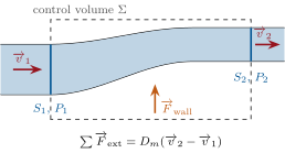
For a steady flow through a control volume with one inlet (section S1, uniform velocity v1) and one outlet (S2, v2), the mass flow rateDm being the same at both,
∑Fext=Dm(v2−v1),
where ∑Fext is the sum of all external forces on the fluid inside Σ: weight, forces from walls and bodies in contact with it, and the pressure forces on the inlet and outlet sections (P1S1n1 pushing inward, −P2S2n2 at the outlet). With several inlets and outlets, the right side is the sum of the outgoing momentum fluxesDm,ivi minus the incoming ones.
Proof. Consider the closed system S made of the fluid in Σ at time t plus the slab δm=Dmdt about to enter through S1. At t+dt it consists of the fluid in Σ plus the slab δm that has left through S2. Its momentum went from pΣ(t)+δmv1 to pΣ(t+dt)+δmv2; in steady flow pΣ is constant, so dpS=Dmdt(v2−v1). Newton’s second law for S, whose external forces are (to first order) those on the fluid in Σ, gives the result. ∎
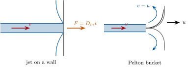
Left: a control volume in a steady flow — the momentum leaving through S2 minus that entering through S1 equals the sum of the external forces on the fluid inside, pressure forces on the two sections included. Right: a jet stopped by a wall pushes it with Dmv; a jet turned back by a Pelton bucket moving at u pushes with up to 2Dm(v−u).
Example 5.3(Jet on a wall; the fire hose)
A jet of section s and speed v strikes a wall perpendicularly and spreads along it: the outgoing momentum along the jet is zero, so the wall receives F=Dmv=ρsv2 — 1.1kN for a 5cm jet at 24m/s. By the same balance applied to the fluid in the hose and nozzle, the nozzle pushes back on the firefighter with Dmv: 20L/s at 30m/s give 600N, the weight of a person. If the wall recedes at u, only Dm′=ρs(v−u) reaches it per unit time and it arrives at the relative speed v−u: F=ρs(v−u)2.
Proposition 5.4(Pelton bucket; rocket thrust)
(i) A jet of speed v and mass flow rateDm is turned back through 180∘ by a bucket moving at u in the jet’s direction: the force on the bucket is F=2Dm(v−u) (with Dm the flow rate actually intercepted by the moving buckets of a wheel), the power Fu is maximal for u=v/2 and then equals 21Dmv2: the jet’s whole kinetic power. (ii) A rocket of mass m(t) ejecting gas backward at the relative speed ve and mass flow rateDm=−dm/dt feels the thrust F=Dmve; in free space its speed increases by Δv=veln(m0/m1) (Tsiolkovsky’s rocket equation); under gravity, mdv/dt=Dmve−mg.
Proof. (i) In the bucket’s frame the jet arrives at v−u and leaves at −(v−u); the momentum balance gives 2Dm(v−u) (the bucket is perfect: no loss of relative speed). Power 2Dmu(v−u), maximal at u=v/2. (ii) Momentum of rocket plus gas ejected in dt: (m+dm)(v+dv)+(−dm)(v−ve)=mv in free space, so mdv=−dmve and v1−v0=veln(m0/m1); with gravity the total momentum changes by −mgdt. ∎
Example 5.5(A launcher)
First stage: Dm=2500kg/s at ve=3000m/s: thrust 7.5MN, which lifts a 600t rocket at 7.5×10⁶/6×105−g=2.7m/s2 off the pad. Burning 500t in 200s gives Δv=3000ln6−9.81×200=5400−2000=3.4km/s — the gravity loss is why launchers climb fast, and the logarithm why they are staged.
Example 5.6(Force on a pipe bend)
Water at P and v in a pipe of section S turns through 90∘. The balance on the fluid in the elbow: Fwall+PSex−PSey=Dm(vey−vex), so the wall pushes the fluid with Fwall=−(PS+ρSv2)(ex−ey) and the fluid pushes the elbow outward with (PS+ρSv2)2. For D=20cm, P=3bar, v=3m/s: PS=9.4kN, ρSv2=0.28kN, force 13.7kN along the bisector — the pressure term dominates, and it is what the anchor blocks of a pipeline hold.
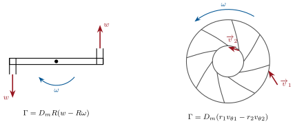
In steady flow, the total moment about a point O of the external forces on the fluid in Σ equals the flux of angular momentum out minus in: ∑MO=Dm(r2∧v2−r1∧v1). For a rotating machine (turbine or pump) of axis Oz, with the fluid entering at radius r1 with azimuthal velocity vθ1 and leaving at r2 with vθ2, the torque exerted by the fluid on the rotor and the power it delivers are
A turbine takes the swirl out of the fluid; a pump puts it in.
Proof. Same closed-system argument with r∧v in place of v. The torque on the rotor is the opposite of the torque of the rotor on the fluid; the pressure forces on the inlet and outlet surfaces (which are surfaces of revolution) have no moment about the axis. ∎
Example 5.8(The lawn sprinkler)
Two arms of length R eject water tangentially at the relative speed w; the sprinkler turns at ω. Water enters on the axis with no angular momentum and leaves with rvθ=R(w−Rω) (absolute azimuthal speed w−Rω, opposite to the rotation): the torque on the arms is DmR(w−Rω). At rest it is DmRw; with no friction the sprinkler accelerates until Rω=w — the water leaves with zero absolute speed and the torque vanishes; with a friction torque Γf it settles at ω=(w−Γf/DmR)/R.
Left: the lawn sprinkler — water leaves the arms tangentially at the relative speed w; the outgoing angular momentum turns the arms the other way. Right: a radial-inflow turbine (a Francis runner seen along its axis): the fluid enters at the rim with a large swirl and leaves near the axis with little; the difference of angular momentum flux is the torque on the runner.
5.3 Energy balance: pumps, turbines and losses
Theorem 5.9(Mechanical energy balance of a steady flow)
For an incompressible fluid in steady flow through a machine (pump or turbine) between an inlet 1 and an outlet 2, with Pu the mechanical power delivered to the fluid by moving parts (positive for a pump, negative for a turbine) and Pdiss≥0 the power dissipated by viscosity,
Dividing by ρgDV gives the balance in heads (metres of fluid): H2−H1=Hpump−Hloss, with H=P/ρg+v2/2g+z. For a perfect fluid with no machine this is Bernoulli; the hydraulic power of a pump raising the head by Hpump is ρgDVHpump.
Proof. Kinetic energy theorem for the closed system of the proof of Theorem 5.2: in dt its kinetic energy changes by Dmdt(v22−v12)/2; the work done on it is that of gravity, −Dmdtg(z2−z1), of the pressure forces on the moving end faces, (P1S1v1−P2S2v2)dt=(P1−P2)DVdt, of the moving parts, Pudt, and of the internal viscous forces, −Pdissdt (the walls, at rest, do no work). Divide by dt. ∎
Example 5.10(Sizing a pump)
Water is to be lifted 30m at 20L/s through 100m of 10cm pipe (λ=0.02): v=2.5m/s, head loss λ(L/D)v2/2g=0.02×1000×0.32=6.4m, exit kinetic head 0.32m: Hpump=36.7m, hydraulic powerρgDVH=7.2kW, and 10kW of electricity at 70% efficiency. The pressure at the pump outlet is ρgHpump≈3.6bar above the inlet.
Proposition 5.11(Sudden expansion: the Borda–Carnot loss)
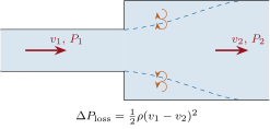
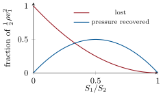
When a pipe of section S1 opens suddenly into a pipe of section S2>S1, the jet spreads in a turbulent zone and the pressure rises downstream, but less than Bernoulli would say: the mechanical energy lost per unit volume is
ΔPloss=21ρ(v1−v2)2,
the kinetic energy of the "lost" relative velocity. A flow leaving a pipe into a large tank (v2→0) loses all its kinetic energy.
Proof. Momentum balance on the fluid between the expansion and a section downstream where the flow is again uniform; experiment shows the pressure on the annular wall at the expansion to be P1 (the jet has not yet spread). Hence (P1−P2)S2=Dm(v2−v1)=ρS2v2(v2−v1), i.e. P2−P1=ρv2(v1−v2). Bernoulli would give 21ρ(v12−v22); the difference is 21ρ(v1−v2)2. ∎
Left: a sudden expansion — the jet spreads in a turbulent dead zone and part of its kinetic energy is dissipated. Right: the fractions of the upstream kinetic energy lost and recovered as pressure, against the section ratio; the loss is largest for a jet into a tank.
Method 5.12(Setting up a balance)
(1) Draw the control volume: its boundary should cut the flow only where the velocity and pressure are known or wanted (uniform sections, free jets at P0, free surfaces). (2) List the external forces on the fluid inside: weight, wall forces (unknown, the usual target), pressure on the cut sections. (3) Write the momentum flux out minus in; for moving parts, work in the frame of the part if the flow is steady there. (4) For torques, the angular-momentum balance; for powers, the energy balance in heads. (5) The force on the wall is minus the force of the wall on the fluid; add the atmospheric pressure acting on the outside of the device if the net force on the device is wanted.
5.4 Exercises
Exercise 5.1★
A fire hose delivers 25L/s through a nozzle of 3.0cm diameter. Exit speed; reaction force on the nozzle; force of the jet on a wall it hits perpendicularly; on a wall receding at 10m/s.
Solution
Solution of Exercise 5.1.
s=7.1cm2, v=0.025/7.1×10−4=35m/s; F=Dmv=25×35=880N on the nozzle and on the wall; receding wall: ρs(v−u)2=1000×7.1×10−4×25.42=460N.
Exercise 5.2★
A rocket engine ejects 250kg/s at 3.0km/s. Thrust; initial acceleration of a 60t rocket; acceleration when 40t of propellant have burned; speed gained after that burn (free space, then with gravity, duration 160s).
Solution
Solution of Exercise 5.2.
F=250×3000=750kN; a0=750/60−9.81=2.7m/s2; at 20t: 37.5−9.8=28m/s2. Δv=3000ln3=3.3km/s in free space; minus gτ=1.6km/s: 1.7km/s.
Exercise 5.3★
Water flows at 2.0m/s and 4.0bar in a 15cm pipe that turns through 90∘. Force exerted by the water on the elbow (magnitude and direction); which part comes from the pressure, which from the momentum change? Same elbow with the pipe open to the air just after the bend.
Solution
Solution of Exercise 5.3.
S=177cm2: PS=7.1kN, ρSv2=71N. Each component of the force on the elbow is PS+ρSv2=7.1kN: 10kN along the outward bisector, 99% of it pressure. Open outlet (gauge pressure zero there): 7.1 kN along the inlet direction and 71N along the outlet: 7.1kN, almost along the inlet axis.
Exercise 5.4★
A jet engine on a test stand swallows 80kg/s of still air and exhausts it at 550m/s (fuel mass negligible). Thrust. In flight at 240m/s, same exhaust speed relative to the engine: thrust, propulsive power, and the kinetic power given to the air in the engine frame; propulsive efficiency.
Pelton wheel. A jet of 0.50m3/s at 60m/s hits the buckets of a wheel of radius 0.80m. (a) Force and power on the buckets at bucket speed u (perfect 180∘ deflection); optimal u and the corresponding rotation speed in rpm. (b) Power and efficiency at the optimum. (c) Real buckets deflect the jet by 165∘: force and power at u=v/2; efficiency. (d) Torque at the optimum; what happens to the torque at standstill and at the runaway speed?
Solution
Solution of Exercise 5.5.
Dm=500kg/s. (a) F=1000(60−u) N, P=1000u(60−u); u=30m/s, ω=37.5 rad/s =360rpm. (b) 900kW=21Dmv2: 100%. (c) F=Dm(v−u)(1+cos15∘)=29.5kN, P=885kW, 98%. (d) Γ=FR=24kNm; at standstill the force doubles (Γ=48kNm); at u=v force and torque vanish.
Exercise 5.6★★
Sprinkler. Two arms of 15cm end in 3.0mm nozzles; the total flow is 0.20L/s. (a) Relative exit speed. (b) Torque at rest. (c) Rotation rate with a bearing friction torque of 5.0×10⁻³Nm; the limiting rate with no friction. (d) Absolute speed of the water leaving, in each case.
Solution
Solution of Exercise 5.6.
(a) s=7.1mm2 per nozzle, 0.10L/s each: w=14m/s. (b) Γ0=DmRw=0.2×0.15×14=0.42Nm. (c) DmR(w−Rω)=5×10⁻³: w−Rω=0.17m/s, ω=93rad/s≈890rpm; without friction Rω=w: 900rpm. (d) 0.17m/s backward, then zero: the water drops straight down.
Exercise 5.7★★
Hovering. A helicopter of 2.0t hovers with a rotor of 10m diameter. Model the rotor as a disk that takes in still air and pushes it down through a uniform speed vi at the disk, 2vi far below (admit the factor 2). (a) Thrust in terms of ρ, A, vi; value of vi. (b) Power given to the air (its kinetic power far below). (c) Why does a larger rotor need less power? (d) Same calculation for a 1kg drone with four 25cm propellers; power-to-weight ratio compared.
Solution
Solution of Exercise 5.7.
(a) Dm=ρAvi, momentum fluxDm⋅2vi: T=2ρAvi2; A=78.5m2, T=19.6kN: vi=10m/s. (b) P=21Dm(2vi)2=Tvi=200kW. (c) P=T3/2/2ρA: doubling the area divides the induced power by 2 — a bigger rotor moves more air more slowly. (d) A=0.20m2, vi=9.81/0.47=4.6m/s, P=45W: 45W/kg against 100W/kg — the disk loading T/A is lower.
Exercise 5.8★★
Sudden expansion. Water at 4.0m/s in a 5cm pipe enters a 10cm pipe. (a) Downstream speed; pressure rise according to Bernoulli and according to Borda–Carnot; loss in pascals and in metres of head. (b) The same expansion made gradual (a diffuser) recovers 80% of the Bernoulli rise: loss. (c) Loss when the 5cm pipe discharges into a large tank. (d) Power lost in case (a) and (c) at the given flow.
Solution
Solution of Exercise 5.8.
(a) v2=1.0m/s; Bernoulli 21ρ(16−1)=7.5kPa; actual ρv2(v1−v2)=3.0kPa; loss 4.5kPa=0.46m. (b) 6 kPa recovered, 1.5kPa lost. (c) 21ρv12=8kPa, 0.82m. (d) DV=7.9L/s: 35W and 63W.
Exercise 5.9★★
A pump draws water from a well 5.0m below it and delivers 10L/s to a tank 25m above it through 60m of 6cm pipe (λ=0.025, plus a singular loss of 2v2/2g for the fittings). (a) Speed and losses. (b) Pump head and hydraulic power; shaft power at 65% efficiency. (c) Pressure at the pump inlet (suction side) and outlet. (d) The water’s vapour pressure is 2.3kPa: maximum height of the pump above the well.
Solution
Solution of Exercise 5.9.
(a) v=0.01/2.83×10−3=3.5m/s, v2/2g=0.64m; friction 0.025×1000×0.64=16m, fittings 1.3m: 17.3m. (b) H=30+17.3+0.64=48m; ρgDVH=4.7kW; 7.2kW at the shaft. (c) Inlet (no suction losses): P0−ρg(5+0.64)=45kPa; outlet 45+470=515kPa. (d) Pin≥2.3kPa: h≤(100−2.3)/9.81−0.64=9.3m (less with suction losses; 7–8m in practice).
Exercise 5.10★★★
Water rocket. A 2.0L bottle holds 1.0L of water and air at 5.0bar (absolute); the nozzle has a diameter of 2.2cm; empty bottle 0.10kg. (a) Initial exit speed (Bernoulli, water surface at rest) and thrust; initial acceleration. (b) As water leaves the air expands isothermally: pressure and exit speed when half the water is gone. (c) Estimate the burn duration and the speed reached (neglect gravity and drag, treat the thrust as its mean value). (d) What does the empty bottle do once the water is gone, and why does a little water (not a lot) give the best height?
Solution
Solution of Exercise 5.10.
(a) v=2×4×105/1000=28m/s; s=3.8cm2, Dm=10.8kg/s, F=Dmv=2ΔPs=300N; a=300/1.1−9.8=260m/s2. (b) Air at 1.5L: P=3.3bar, v=2×2.3×105/1000=22m/s. (c) Mean exit speed ≈22m/s: burn ≈10−3/(3.8×10−4×22)=0.12s; rocket equation with ve≈22m/s: Δv≈22ln(1.1/0.1)=50m/s. (d) The remaining 2.5bar of air blows out and adds a little; too much water leaves little air and the pressure collapses early, too little leaves little mass to throw — about a third of the volume is best.
Exercise 5.11★★★
Francis turbine. Water enters a runner at r1=1.0m with vθ1=20m/s and leaves at r2=0.50m with no swirl; flow 30m3/s; rotation 150rpm. (a) Torque and power. (b) Head extracted, H=P/ρgDV. (c) If the runner ran at 200rpm with the same inlet velocity and the exit swirl became vθ2=3m/s in the direction of rotation: power and the fraction of the head turned into useless exit swirl. (d) Why is the Pelton wheel used for high heads and small flows, the Francis for the opposite?
Solution
Solution of Exercise 5.11.
(a) Γ=Dmr1vθ1=3×104×20=600kNm, ω=15.7 rad/s, P=9.4MW. (b) H=P/ρgDV=32m. (c) Γ=3×10⁴(20−1.5)=555kNm, P=11.6MW (head 39m); the exit swirl carries vθ22/2g=0.46m, about 1%. (d) A Pelton jet is at atmospheric pressure: it needs a high head to be fast, and its flow is limited by the nozzle; a Francis runner is full of water under pressure and passes large flows at moderate heads.
Exercise 5.12★★★
Hydraulic jump. In a horizontal channel of unit width, water of depth h1 flowing at v1 jumps abruptly to depth h2 and speed v2 (the foamy step below a weir or in a kitchen sink). (a) Mass conservation. (b) Momentum balance on the fluid between the two sides of the jump, the pressure being hydrostatic on each side: show 21gh12+v12h1=21gh22+v22h2. (c) Deduce h2/h1=21(−1+1+8Fr12) with Fr1=v1/gh1 (the Froude number); a jump needs Fr1>1. (d) Head lost in the jump, ΔH=(h2−h1)3/4h1h2; numbers for h1=0.20m, v1=4.0m/s, and the power dissipated per metre of width.
Solution
Solution of Exercise 5.12.
(a) v1h1=v2h2=q. (b) Hydrostatic force per unit width on a section ∫0hρg(h−z)dz=21ρgh2; momentum: 21ρg(h12−h22)=ρq(v2−v1); divide by ρ and use q=v1h1=v2h2. (c) With v2=v1h1/h2 and h1=h2: 21g(h1+h2)h2=v12h1, i.e. (h2/h1)2+h2/h1−2Fr12=0; h2>h1 needs Fr1>1. (d) ΔH=(h1+v12/2g)−(h2+v22/2g)=(h2−h1)3/4h1h2. Fr1=2.86, h2/h1=3.57, h2=0.71m, v2=1.1m/s, ΔH=0.5143/0.57=0.24m; ρgqΔH=1.9kW per metre of width.
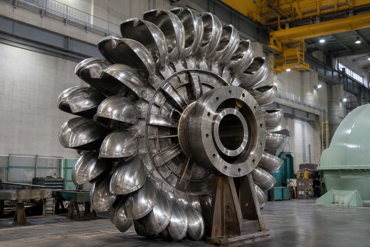
The runner of a Pelton turbine: each bucket turns the jet back through nearly 180∘, and the change of the water’s momentum is the force on the wheel.
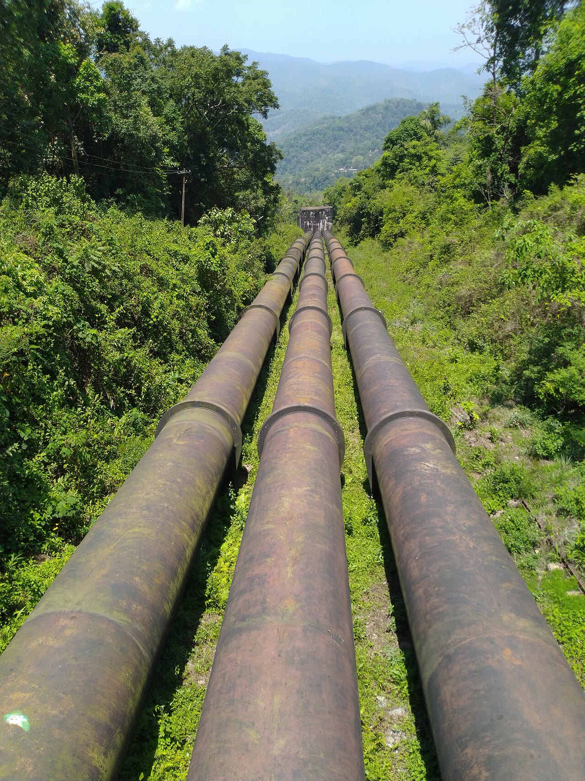
The penstocks of a hydroelectric plant feed the turbines below: the momentum balance of the jet on the buckets of a Pelton wheel turns the head of water into shaft work.
5.5 Problem: Jets, rockets and runners
Problem 5.1
Weekend problem — what pushes a jet aircraft, what lifts a rocket, what turns a turbine, and what it costs to pump water uphill
Part I — The turbojet. An engine on a test stand takes in Da=50kg/s of still air, burns Df=1.0kg/s of fuel, and exhausts the mixture at ve=600m/s at atmospheric pressure.
Thrust on the test stand.
In flight at v=250m/s (same ve relative to the engine): thrust, and the propulsive power Fv.
Kinetic power given to the gas, computed in the engine’s frame. Propulsive efficiency ηp=Fv/Pkin; show that, neglecting the fuel mass, ηp=2v/(v+ve).
The fuel releases 43MJ/kg: thermal efficiency of the engine (kinetic power over heat power) and overall efficiency.
A turbofan uses the same kinetic power to accelerate 500kg/s of air: exhaust speed, thrust and ηp at 250m/s. Why do airliners have huge fans?
Why can a turbojet not work at rest on a rocket’s job, above the atmosphere?
Reverse thrust on landing deflects the fan flow forward at 45∘ from the axis: braking force for the turbofan of question 5 at 70m/s, the fan exhaust being then 150m/s relative to the engine; compare with the forward thrust the same flow would give.
Part II — The rocket. A single-stage rocket: initial mass m0=300t, propellant 200t, exhaust speed ve=3.0km/s, burn time τ=150s at constant mass flow rate.
Apply the momentum balance to rocket plus the gas ejected in dt to derive mdv/dt=Dmve−mg for a vertical flight.
Mass flow rate, thrust, and the acceleration at lift-off and at burn-out.
Integrate to get the burn-out speed; what is the "gravity loss"?
Burn-out speed with the same rocket split into two stages of 100t of propellant each, the first stage’s empty mass (20t) being dropped before the second ignites (neglect gravity here): compare with the single stage.
What exhaust speed would a single stage need to reach orbital speed (7.8km/s, neglecting gravity) with the same mass ratio? Comment on the choice of propellants.
At lift-off the exhaust jet (1333kg/s at 3km/s) hits the flame deflector of the pad and is turned horizontally: force on the deflector.
The rocket’s exhaust is also a fluid flow: why does the thrust increase with altitude for a real nozzle (think of the pressure on the nozzle exit section)?
Part III — The Pelton wheel. The jet of the previous chapter’s plant: DV=60m3/s at v=62.6m/s, split between two wheels; each wheel has a radius R=1.5m and buckets deflecting the jet by 165∘.
Force on the buckets of one wheel at bucket speed u, and the power; optimal u.
Rotation speed at the optimum, in rpm; torque on the shaft.
The generator must turn at a multiple of 50Hz divided by its number of pole pairs: choose the number of pole pairs.
Power of one wheel and efficiency with respect to the jet’s kinetic power; total electrical power at 95% generator efficiency.
Using the angular-momentum balance (Euler’s turbine equation) on a bucket at the optimum: angular momentum of the water entering and leaving, per kilogram, and check the torque.
The load drops suddenly and the wheel runs away toward u=v: what happens to the force and to the torque, and why is a deflector that diverts the jet part of every Pelton plant?
Part IV — Pumping uphill. The plant is also used as storage: at night 40m3/s are pumped back up through the penstock (400m, 3m, λ=0.015) to the reservoir 200m above.
Head losses in the penstock at 40m3/s; pump head needed.
Hydraulic power, and electrical power drawn at 88% pump efficiency.
Pressure at the bottom of the penstock while pumping; compare with its value in turbine mode (previous chapter).
Energy stored per night of 8h (potential energy of the water raised); round-trip efficiency of the storage if the turbine mode recovers 90% of the available head and the generator 95%.
Sum up the four balances used in this problem (momentum, angular momentum, energy, mass) and the device each one sized.
Solution
Solution of Problem 5.1.
1.F=(Da+Df)ve=51×600=30.6kN.
2.F=51×600−50×250=18.1kN; Fv=4.5MW.
3.Pkin=21×51×6002−21×50×2502=7.6MW; ηp=0.59. With Df=0: ηp=2v(ve−v)/(ve2−v2)=2v/(ve+v)=500/850.
5.21×500(ve′2−2502)=7.6×10⁶: ve′=305m/s; F=500×55=27.5kN; ηp=500/555=0.90. Moving more air more slowly gives more thrust for the same power: hence the fans.
6. It needs the outside air both as working fluid and as oxidizer; a rocket carries both.
7. Air enters at 70m/s (backward in the engine’s frame) and leaves with a forward component 150cos45∘=106m/s: the momentum given to the air is forward, 500(106+70)=88kN of braking; the same flow exhausted backward would give 500(150−70)=40kN of thrust.
8. Over dt the system (rocket m + gas Dmdt ejected at v−ve): (m−Dmdt)(v+dv)+Dmdt(v−ve)−mv=−mgdt, hence mdv/dt=Dmve−mg.
9.Dm=1333kg/s; F=4.0MN; a=13.3−9.8=3.5m/s2 at lift-off, 40−9.8=30m/s2 at burn-out.
10.v=veln(m0/m)−gt: 3000ln3−9.81×150=3296−1472=1.8km/s; the gravity loss is 1.5km/s.
11. Stage 1: 3000ln(300/200)=1.2km/s; drop 20t; stage 2: 3000ln(180/80)=2.4km/s: 3.6km/s against 3.3km/s for the single stage (with gravity the gap widens).
12.ve=7800/ln3=7.1km/s: no chemical propellant reaches it (hydrogen–oxygen gives 4.5km/s); staging is compulsory.
13. The jet’s vertical momentum fluxDmv=4.0MN is removed and an equal horizontal one created: a 4MN downward force plus 4MN sideways, 5.7MN in all.
14. The balance on the engine includes (Pe−P0)Se on the exit section; as P0 falls with altitude this term grows: the thrust rises by some 10–15% in vacuum.
15.Dm=3×10⁴kg/s per wheel: F=Dm(v−u)(1+cos15∘)=1.97×3×104(62.6−u); P=Fu, maximal at u=v/2=31.3m/s.
18.P=Fu=58MW; jet power 21Dmv2=59MW: 98%; 2×58×0.95=110MW.
19. In: Rv=94m2/s per kg. Out: absolute azimuthal speed u−(v−u)cos15∘=1.1m/s, i.e. 1.6m2/s. Γ=Dm(94−1.6)=2.8MNm — as in 16.
20. As u→v the relative speed, the force and the torque vanish: nothing brakes the wheel, which overspeeds; the deflector throws the jet off the buckets within a second while the needle valve closes slowly enough to avoid water hammer.
21.v=5.7m/s, v2/2g=1.6m; loss 0.015×133×1.6=3.3m; pump head 200+3.3+1.6=205m.
22.ρgDVH=9810×40×205=80MW; 91MW electrical.
23.P=P0+ρg(200+3.3)+21ρv2≈21bar absolute, against 20.3bar in turbine mode: the losses now add to the static head instead of subtracting.
25. Momentum: the jet engine’s and the rocket’s thrust, the Pelton force. Angular momentum: the turbine torque (Euler). Energy: the pump head and power, the storage efficiency. Mass: every flow rate, the rocket’s mass loss.