University Physics — Year 2 · Bachelor Year 2
20The Michelson Interferometer
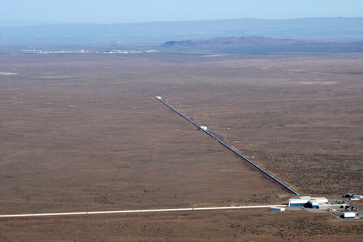
In 1887 Michelson and Morley split a beam of light in two, sent the halves along perpendicular arms, recombined them, and watched the fringes for the shift that the Earth’s motion through the ether should produce: nothing moved, and physics changed. In 2015 the same instrument — two arms, now four kilometres long and folded to a thousand — recorded a gravitational wave that changed their lengths by a thousandth of a proton’s diameter. Between those two dates the Michelson interferometer measured the metre in wavelengths, resolved spectral lines, and became the standard tool of precision optics. This chapter describes it in its two configurations — the air wedge and the parallel plate — and shows how its fringes measure lengths, indices and spectra.
20.1 The instrument
Definition 20.1 (The Michelson interferometer)
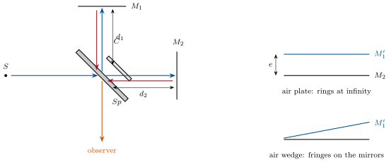
A beam splitter — a glass plate with a semi-reflecting face — at divides an incident beam into two: one goes to the mirror , the other to , both perpendicular to their beams; after reflection each returns to , where half of it is sent toward the observer, where the two halves interfere. A compensating plate , identical to the splitter and parallel to it, is put in the arm that would otherwise cross the splitter’s glass only once, so that both beams cross the same thickness of glass: the path difference is then a pure difference of air paths, the same for every wavelength — which white-light fringes require. The mirrors’ distances from are and ; one mirror is mounted on a micrometer screw and on tilt screws.
Proposition 20.2 (Equivalent arrangement)
Seen from the observer, the interferometer is equivalent to the mirror and the image of in the splitter: a thin layer of air between two reflecting surfaces, of thickness , whose two reflections interfere (division of amplitude):
- : an air plate of thickness — rings of equal inclination, localized at infinity, ;
- slightly tilted by relative to : an air wedge — straight fringes of equal thickness, localized on the mirrors (near the wedge), at normal incidence, spacing .
At contact (, ) the field is uniform, and for white light it is the one place where the colours agree: the "white fringe".
Proof. Folding the arm onto the arm by reflection in maps the two beams onto one line with two mirrors apart; the two returning waves are those reflected by the two faces of the air layer (no extra : both reflect on metal, and the splitter treats them symmetrically, up to a constant phase that shifts the whole pattern). The thin-film results of Chapter 19 then apply with . ∎
20.2 The two fringe systems
Proposition 20.3 (Rings of the air plate)
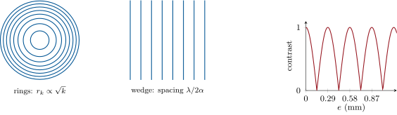
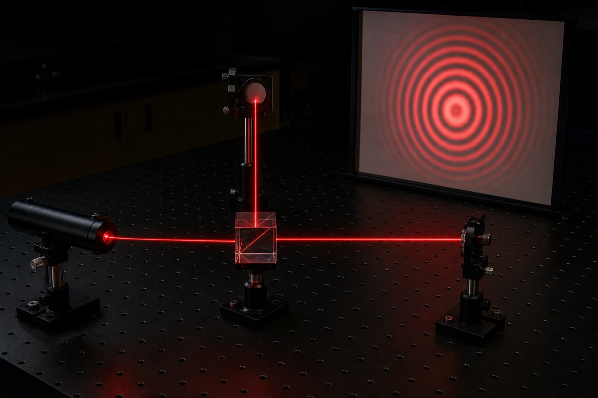
With and an extended source, the observer (or a lens of focal length and a screen in its focal plane) sees concentric rings; the ring at the angle has the order ; bright rings where is an integer. The centre has the highest order, ; near it, , so the -th bright ring from the centre (counted from the first one, at below the centre’s order) has the radius
rings tighter with larger (more, thinner rings), spreading as until, at contact, one uniform field. Moving a mirror by changes by one: a ring is born at (or swallowed by) the centre for every half wavelength of displacement.
Proof. for the parallel plate (Chapter 19, , no extra for two metallic reflections); with gives . ∎
Proposition 20.4 (Fringes of the air wedge)
With tilted by a small angle and near-normal incidence, the path difference at the point of the mirrors at distance from the line of contact is : straight fringes parallel to that line, spaced , localized on the mirrors (they are viewed by focusing on , or projected on a screen with a lens conjugating and the screen). The zero-order fringe lies on the contact line, the same for every wavelength: with white light it is white (or black, according to the splitter’s phases), flanked by a few coloured fringes — the signature by which the contact is found.
Proof. Equal-thickness fringes of a wedge of air, . Localization: for an extended source the rays through a given point of the wedge recombine there, with the same at near-normal incidence. ∎
20.3 Measuring with the Michelson
Proposition 20.5 (Lengths, indices, spectra)
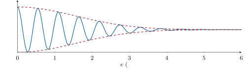
Counting fringes passing the centre while a mirror moves by gives : lengths in wavelengths (a micrometre screw calibrated to ; the metre itself was so measured). A transparent plate of thickness and index inserted in one arm adds to and shifts the pattern by fringes: indices (and their variations with pressure or temperature, in a gas cell). With a doublet of wavelengths and , the two fringe systems fall out of step and back in step as grows, the contrast vanishing every
the splitting of close lines. More generally the contrast as a function of maps out the spectrum of the source (the contrast decays over ): recording the intensity at the centre while scans is Fourier transform spectroscopy, the method of infrared spectrometers.
Proof. The order at the centre is ; each line has its own. The two systems coincide again when , i.e. ; they are in opposition half-way. The general statement is the contrast formula of Exercise 18.10. ∎
Example 20.6 (Sodium, and the metre)
The sodium doublet ( at ): the rings blur and sharpen every nm — a classic measurement of to a few percent with a screw. Michelson (1892) counted the fringes of the red cadmium line over the length of the standard metre: wavelengths, the first tie between the metre and an atom; today the metre is defined through and the second, and interferometers check gauge blocks in production to nanometres.
Remark 20.7 (The arms that measured nothing, and those that measured a wave)
Michelson and Morley expected the Earth’s velocity through the ether to change the round-trip time along the arm parallel to it by relative to the perpendicular arm, a fringe shift of fringe for and ; rotating the apparatus should have swung the pattern by that much. They could see fringe; they saw nothing. The gravitational-wave detectors of today are Michelsons with arms, light bouncing some three hundred times in each, and a laser stable enough to read a change of arm length — m, a thousandth of a proton — against the noise of seismic motion and of the photons themselves.
Method 20.8 (Using a Michelson)
(1) Identify the configuration: parallel plate (rings at infinity; observe with a lens or the eye at infinity) or wedge (fringes on the mirrors; focus on ). (2) Write or and the order. (3) Translate each measurement into fringes: , for a plate, for a doublet. (4) Use the contact position (, white fringe) as the absolute reference; note that the rings’ radii shrink as grows. (5) Coherence limits: rings are visible while ; the wedge needs near-normal incidence.
20.4 Exercises
Exercise 20.1 ★
A Michelson in sodium light (): the mirror is moved by : number of rings passing the centre; displacement corresponding to fringes; precision on if a tenth of a fringe can be read.
Solution
Solution of Exercise 20.1.
; fringes: ; a tenth of a fringe is .
Exercise 20.2 ★
Parallel plate of thickness , lens , : order at the centre; is the centre bright? Radii of the first three bright rings; what happens to the rings as is reduced to ?
Solution
Solution of Exercise 20.2.
: not an integer, the centre is not bright (). : , , . At the radii grow by : few, broad rings.
Exercise 20.3 ★
Air wedge with , : fringe spacing; number of fringes across of mirror; the wedge angle is doubled: what happens? How is the contact found with white light?
Solution
Solution of Exercise 20.3.
; six fringes across ; doubling halves the spacing. Contact: translate the mirror until the white-light fringes (a white one flanked by coloured ones) appear — they exist only within a micrometre of .
Exercise 20.4 ★
A glass plate thick is inserted in one arm: fringe shift for at ; the shift is measured to fringe: precision on . Why could the same measurement not be made with white light if the plate were thick?
Solution
Solution of Exercise 20.4.
fringes; fringe gives . A centimetre of glass adds millimetres of dispersive path: the colours no longer agree anywhere, no white fringe.
Exercise 20.5 ★★
Sodium doublet. (a) Thickness between two successive disappearances of the rings, for . (b) A student measures disappearances over : and its precision. (c) Orders of the two lines at : check they differ by . (d) Why is the contrast never exactly zero (the two lines have intensities in the ratio ): minimum contrast.
Solution
Solution of Exercise 20.5.
(a) . (b) : ; : . (c) At (the first disappearance): , — half an order apart; at they differ by one. (d) The weaker fringes survive: .
Exercise 20.6 ★★
Index of air. A cell in one arm is evacuated, then slowly filled with air at ; fringes pass (). (a) for air. (b) Fringes passing for a change of pressure; temperature coefficient if . (c) Why does this matter for the stability of any interferometer in air? (d) Precision on from a tenth of a fringe.
Solution
Solution of Exercise 20.6.
(a) : . (b) fringe per percent; . (c) A few millibars or a degree in one arm move the fringes: hence vacuum or equal arms. (d) : .
Exercise 20.7 ★★
Coherence length. With a low-pressure mercury lamp (green line, , width ) the rings fade as grows. (a) Coherence length; thickness at which the contrast becomes negligible. (b) Same with a high-pressure lamp (). (c) With a He–Ne laser (): can one still see rings with ? (d) What limits white-light fringes to orders around contact?
Solution
Solution of Exercise 20.7.
(a) : rings fade beyond . (b) , . (c) : yes. (d) : , a couple of orders.
Exercise 20.8 ★★
Compensating plate. Without , one beam crosses the splitter’s glass (, ) three times and the other once. (a) Extra optical path; can it be compensated by moving a mirror for monochromatic light? (b) Why not for white light (dispersion: varies by across the visible)? (c) What tolerance on the parallelism of and keeps the white fringe (take a residual difference of thickness )? (d) Modern splitters are thin pellicles or cubes: why is unnecessary then?
Solution
Solution of Exercise 20.8.
(a) ; yes, by of mirror travel. (b) The glass path varies with by : no wavelength-independent zero. (c) : — a relative tilt below over . (d) A pellicle is micrometres thick; a cube is symmetric: both beams see the same glass.
Exercise 20.9 ★★
Michelson–Morley. Arms of (folded), , Earth’s orbital speed . (a) In the ether theory the round trip along the arm parallel to takes and the perpendicular one : difference, to lowest order. (b) Fringe shift expected on rotating the apparatus by (the roles of the arms swap). (c) They could detect fringe: upper bound on . (d) What does a null result say, and what did Einstein conclude?
Solution
Solution of Exercise 20.9.
(a) , a path of . (b) Swapping the arms doubles it: fringe. (c) . (d) No motion through an ether is seen; the speed of light is the same along both arms — the postulate of relativity.
Exercise 20.10 ★★★
Fourier spectroscopy. The intensity at the centre of the rings is for a source of spectrum . (a) For a single line: ; period in . (b) For a Gaussian line of width : show the fringes have a Gaussian envelope of width in (admit the Fourier transform of a Gaussian is a Gaussian). (c) Resolution: two lines apart are separated if the scan reaches ; for , the resolving power at . (d) Why is this method preferred in the infrared (signal, "multiplex" advantage)?
Solution
Solution of Exercise 20.10.
(a) , period in . (b) Each frequency gives a fringe of slightly different period; a Gaussian band of width sums to fringes with a Gaussian envelope of width . (c) . (d) All wavelengths fall on one detector at once (Fellgett) through a wide aperture (Jacquinot): far more signal than a slit spectrometer in the photon-starved infrared.
Exercise 20.11 ★★★
Gravitational-wave detector. Arms , light recycled to round trips, , the wave changes the arms by in opposite directions. (a) Change of path difference; phase shift. (b) The instrument is held on a dark fringe and measures the small intensity : intensity change for the signal. (c) With of circulating light at , photons per second; the photon noise in () against the signal: is it detectable? What does more power buy? (d) Why are the arms kilometres long, and why the mirrors suspended?
Solution
Solution of Exercise 20.11.
(a) Each arm’s path changes by , in opposite senses: , . (b) Near a dark fringe the detector sees an intensity proportional to — or, with a small offset, to : a relative change of order . (c) photons per second, per millisecond, relative noise : the signal is twenty times the noise; more power lowers the noise as . (d) ; the pendulum suspensions filter the ground’s motion above their resonance.
Exercise 20.12 ★★★
Localization. (a) Show that for the wedge the two rays leaving a point of for an observer at infinity (incidence ) have the path difference plus a term that cancels for : the fringes are on the mirrors at normal incidence only. (b) An extended source illuminates the wedge with incidences up to : what must satisfy for the fringes to stay sharp ( at the edge of the field, )? (c) For the parallel plate the rings do not move when the eye moves: why? (d) A student sees fringes that drift when she moves her head: which configuration is she in, and what should she adjust?
Solution
Solution of Exercise 20.12.
(a) For a point at depth and incidence , plus a term from the tilted second reflection, which vanishes at normal incidence: only there do both rays from reach the eye — localization on the mirrors. (b) : . (c) The rings depend on alone: any eye position sees the same angular pattern. (d) The wedge viewed off the mirrors; focus on or reduce the tilt.
20.5 Problem: The sodium doublet and the index of air
Problem 20.1
Weekend problem — a complete measurement session on a Michelson interferometer: finding contact, reading lengths, splitting the yellow line, weighing the air
The interferometer has a micrometer screw reading ; the sodium lamp gives and with intensities ; a white lamp and a He–Ne laser () are also available.
Part I — Setting up.
- With the laser, the student sees two spots of the two arms on a card; she superposes them with the tilt screws and then sees straight fringes: which configuration is this, and what does their spacing tell about the residual tilt (spacing )?
- Turning the tilt screws, the fringes curve and then become rings: why do rings appear, and where is now?
- She translates the mirror and counts rings swallowed by the centre: displacement; in which direction is changing?
- As she goes on, the rings spread and the central spot grows to fill the field: what has she reached? The sodium lamp replaces the laser and she sees nothing special: why not, and why does white light show a bright central fringe flanked by coloured ones at that point?
- She tilts very slightly at contact and sees, in white light, straight coloured fringes: explain, and say how many she can expect on each side of the white one.
- The laser spots are across and she wants ten rings in the field of a lens of (): thickness needed (use the radius of the -th ring).
- Why must the compensating plate be parallel to the splitter, and what would she see in white light if it were removed?
Part II — The doublet.
- Starting from contact with the sodium lamp, she increases : the rings’ contrast falls, vanishes, returns. Thickness of the first disappearance; of the -th.
- She records disappearances between and (the first and the last read on the screw): ; precision if each reading is good to .
- Orders and of the two lines at the first disappearance; at the first return of full contrast.
- Minimum contrast at a disappearance, given the intensity ratio (the weaker line’s fringes remain).
- How many disappearances can she count before the natural width of the lines ( each) washes everything out?
- What would a lamp with three lines of equal spacing show?
Part III — The air. A cell of length with glass windows is placed in one arm and pumped down; air is let in slowly while the laser fringes are counted.
- Optical path difference created by filling the cell to if ; number of fringes.
- She counts fringes: her value of .
- She lets in only : fringes expected ( pressure).
- The room warms by during the measurement, and the of open air path in each arm change index by per kelvin: fringe drift; is it a problem for Part II, for Part III?
- Why do the cell’s windows not shift the measurement (they are there during the whole count)?
- The experiment is repeated with CO (): fringes for a full cell; how could the gas be identified from the count alone?
Part IV — Limits.
- The screw is read to : precision of a length measured by fringe counting over , versus by the screw alone.
- A vibration of amplitude at shakes one mirror: fringe motion; what does the eye see, what does a camera at frames per second see?
- The laser’s frequency drifts by in relative value during a count over : error in fringes.
- A gauge block is certified to by interferometry: absolute and relative precision.
- Why is the Michelson the instrument of choice for lengths, and the grating (next chapter) for spectra?
- Sum up the four quantities measured (a length, a doublet splitting, an index, a coherence length) and the fringe observation that gave each.
Solution
Solution of Problem 20.1.
1. Wedge fringes; : .
2. has become parallel to : the air plate, whose fringes of equal inclination are rings.
3. ; rings swallowed at the centre: decreasing.
4. Contact, . Sodium light has no feature there (one wavelength, uniform field either way); white light shows the one position where every colour has , flanked by colours as the orders separate.
5. : a white fringe on the contact line and one or two coloured ones on each side ().
6. : .
7. Parallel, the two beams cross equal glass at every wavelength; without , the dispersion of of glass leaves no common zero: no white fringe.
8. ; then every .
9. intervals over : , ; on : .
10. and (half an order apart); at the return, and .
11. .
12. : , about .
13. Three fringe systems: full contrast every , with two partial dips between — the pattern of three slits.
14. : fringes.
15. .
16. fringes.
17. Equal arms: the drift is common to both and cancels; a inequality gives — harmless for both parts.
18. They are present, unchanged, throughout the count: a constant offset.
19. fringes; the count gives , a signature of the gas.
20. fringes over a centimetre, read to a tenth: , ; the screw gives a micrometre.
21. swings by , fringe at : the eye sees lowered contrast; at frames per second the camera samples four periods per frame and sees a frozen or slowly beating pattern.
22. fringe: nothing.
23. on : .
24. It compares a length directly with a wavelength, fringe by fringe; the grating spreads all wavelengths at once over a wide range.
25. Length: rings counted at the centre. Doublet: the periodic loss of contrast. Index: fringes passing while the cell fills. Coherence length: the thickness at which the rings fade.