University Physics — Year 2 · Bachelor Year 2
27Thermodynamic Balances and Open Systems
The thermodynamics of the Year 1 volume dealt with closed systems — a fixed mass of gas in a cylinder, compressed, heated, expanded. But the machines that actually heat our houses, cool our food and make our electricity are crossed by a flow: steam streams through the turbine of a power plant at hundreds of kilograms per second, a refrigerant circulates through the compressor, condenser, valve and evaporator of a heat pump, air flows through the compressor and combustion chamber of a jet engine. Each component is an open system, a region of space with matter entering and leaving, and the first and second laws must be rewritten for it. The rewriting is short — the key is that the fluid pushed into the system carries, besides its internal energy, the work done to push it, which is why enthalpy, not internal energy, is the natural energy of a flow. This chapter establishes the balances of mass, energy and entropy for open systems in steady flow, applies them to the elementary devices — nozzle, throttle, compressor, turbine, heat exchanger — and assembles those devices into the two cycles that the weekend problem sizes: a heat pump and a steam power plant.
27.1 Open systems and the mass balance
Definition 27.1 (Open system, control volume, steady flow)
An open system is a fixed region of space, the control volume , bounded by a surface through which fluid enters and leaves (inlet and outlet sections) and through which heat and work can be exchanged with the outside; the work received through moving parts (a shaft, a piston) other than the flow itself is the useful work (shaft work). The flow is steady when every field inside is time-independent: the mass, energy and entropy contained in are then constant.
Proposition 27.2 (Mass balance)
Through a section of area where the fluid of density moves at the mean speed normal to it flows the mass flow rate (in ). In a steady flow, what enters leaves: ; for a single stream, is the same at inlet and outlet, — the continuity equation of Chapter 2 integrated over the section.
Proof. The mass in is constant, so the fluxes balance. ∎
27.2 The first law for an open system
Theorem 27.3 (Energy balance of a steady single-stream flow)
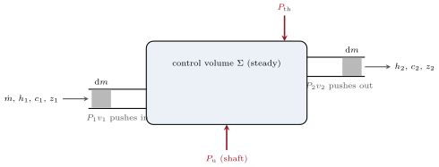
For a steady flow of mass flow rate entering at the state 1 and leaving at the state 2, receiving the useful (shaft) power and the thermal power ,
or, per unit mass of fluid crossing the system,
The enthalpy replaces the internal energy: is the flow work, the work done by the upstream fluid to push a unit mass in, minus that done to push it out.
Proof. Follow the closed system made of the fluid inside at plus the slug about to enter; at it consists of the fluid inside (same state, steady) plus the slug that has left. Its energy changed by . It received , plus the work of the pressure forces at the inlet, (pushing the slug in), minus that at the outlet, . The first law for this closed system, with , gives the result. ∎
Remark 27.4 (Using the first law)
For an ideal gas ; for a liquid (the second term is the pump’s work); for a vapour one reads from tables or charts. The kinetic term is usually negligible: at , , against for one kelvin of air — it matters only in nozzles and turbine blades, where speeds reach hundreds of metres per second. The potential term, per metre, matters for water in a dam, never in a gas cycle. With several inlets and outlets the balance reads (kinetic and potential terms neglected).
27.3 The second law for an open system
Theorem 27.5 (Entropy balance of a steady flow)
For a steady single-stream flow exchanging the thermal powers with sources at the temperatures ,
per unit mass, . An adiabatic reversible flow is isentropic; an adiabatic real flow has . The isentropic efficiency of a turbine is and that of a compressor , where is the state reached isentropically at the same outlet pressure; both are typically –. The work lost to irreversibility, referred to the ambient temperature , is per unit mass.
Proof. Same closed system as before: its entropy changes by , receives from the sources, and the rest is created. ∎
27.4 Elementary devices
Proposition 27.6 (Nozzle, throttle, compressor, turbine, exchanger)
All adiabatic unless stated, steady, kinetic and potential terms neglected unless they are the point.
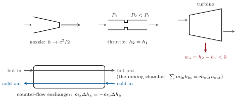
- Nozzle (no shaft, no heat): — enthalpy becomes speed; a diffuser does the reverse.
- Throttle (valve, porous plug; no shaft, no heat, speeds small): , isenthalpic. For an ideal gas ; for a real gas the temperature generally drops (Joule–Thomson effect); for a liquid near saturation a fraction flashes into vapour — the expansion valve of every refrigerator.
- Compressor, pump, turbine (adiabatic machines): — positive for a compressor, negative for a turbine; for a liquid pump , tiny because is small.
- Heat exchanger (two streams, no shaft, adiabatic as a whole): — what one loses the other gains; the exchange creates entropy unless the streams are at the same temperature everywhere (counter-flow reduces it).
- Mixing chamber: .
Proof. Each is the first law with the appropriate terms set to zero. ∎
Example 27.7 (Numbers for the devices)
Steam entering a turbine nozzle at and leaving at reaches . Air compressed adiabatically from , to : isentropically and ; with , and — which is why compressors are cooled between stages. A car radiator removing from water cooled by () warms of air by . Liquid refrigerant at throttled to arrives as a mist with of vapour: the flashing is what cools the liquid to the evaporator temperature.
27.5 Cycles
Proposition 27.8 (Vapour-compression refrigeration and heat pump)
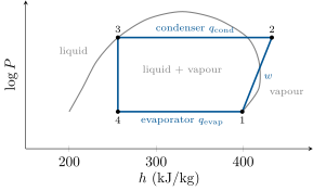
A refrigerant circulates through: (12) an adiabatic compressor that raises the vapour from the evaporator pressure to the condenser pressure, ; (23) a condenser where it releases to the hot side (the room for a heat pump, the kitchen for a fridge) and leaves as a liquid; (34) a throttle, ; (41) an evaporator where it absorbs from the cold side. The coefficients of performance are
bounded by Carnot’s and ; the cycle is read most easily on the diagram, where the two exchanges and the work are horizontal segments.
Proof. The four first-law balances; the energy balance of the whole cycle gives , hence the relation between the two COPs. ∎
Proposition 27.9 (The steam (Rankine) cycle)
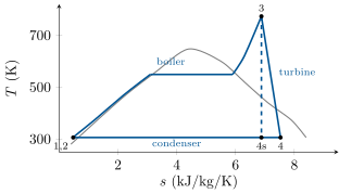
Water circulates through: (12) a pump, , a few ; (23) a boiler at high pressure where it is heated, vaporised and superheated, ; (34) a turbine expanding the steam to the condenser pressure, (a thousand ); (41) a condenser at low pressure where the wet steam turns back to liquid, rejecting to the cooling water. The efficiency is
about – in practice; the heat is added at a mean temperature well below the boiler’s peak, which is why superheating, reheating and high pressures raise , and why the exhaust must stay dry enough () to spare the last blades from droplet erosion.
Proof. First law on each component, then on the cycle: . ∎
Remark 27.10 (Other cycles, and a transient)
The gas turbine (compressor, combustion chamber, turbine: the Brayton cycle) has the ideal efficiency for the pressure ratio and rejects its exhaust at several hundred degrees; feeding that exhaust to a steam cycle (combined cycle) reaches . Open systems also have transients: filling an evacuated rigid tank from a line at ends at (the flow work becomes internal energy), hotter for air — the reason a diving bottle warms as it is filled.
Method 27.11 (Open-system balances)
(1) Draw the control volume; list inlets, outlets, shaft and heat. (2) Mass: . (3) Energy per unit mass: , with for gases, tables for vapours, for pumps. (4) Entropy: , isentropic reference states, efficiencies, lost. (5) Cycles: read the chart, sum around the loop, compare with Carnot.
27.6 Exercises
Exercise 27.1 ★
(a) A garden hose delivers through a nozzle: exit speed. (b) Hot water at , , mixes with cold water at , : outlet temperature. (c) Why is the mixing irreversible — compute the entropy created per second.
Solution
Solution of Exercise 27.1.
(a) . (b) . (c) : heat passed from hot to cold water.
Exercise 27.2 ★
Steam enters a nozzle at with and leaves with : exit speed. Air at accelerated from rest to in a nozzle (): temperature drop. A diffuser slows air from to rest: rise.
Solution
Solution of Exercise 27.2.
; ; .
Exercise 27.3 ★
Throttling. (a) An ideal gas: what happens to , to ? (b) Wet steam at (, ), quality , throttled to (, ): final quality — the throttling calorimeter. (c) Liquid refrigerant at () throttled to (, ): vapour fraction.
Solution
Solution of Exercise 27.3.
(a) unchanged, rises by . (b) : — the quality is read from the temperature of the superheated (or just dry) outlet. (c) .
Exercise 27.4 ★
(a) A radiator cools of water from to ; the air () warms from to : air mass flow and volume flow. (b) A steam turbine, , from to : power. (c) A pump raises water from to : work per kilogram, and power for .
Solution
Solution of Exercise 27.4.
(a) ; , . (b) . (c) ; .
Exercise 27.5 ★★
The flow work. (a) Re-derive the open-system first law and explain where comes from. (b) Why does the internal energy appear in a closed system and in a flow? (c) Compare at and with for of air. (d) Water falling through a penstock: against for ; conclude how much the water warms if the turbine is removed.
Solution
Solution of Exercise 27.5.
(a) Theorem 27.3. (b) A flow is pushed in and out by its neighbours: that pressure work, per unit mass, is bundled with . (c) and against . (d) against : .
Exercise 27.6 ★★
Compressors. Air, , , to ; , , . (a) Isentropic outlet temperature and work. (b) With : work, outlet temperature, entropy created. (c) Two stages of ratio with cooling back to between them: work saved. (d) Isothermal limit ; why real compressors approach it with many stages.
Solution
Solution of Exercise 27.6.
(a) , . (b) , , . (c) Each stage ends at : , saved. (d) ; with intercooling between many stages the path hugs the isotherm.
Exercise 27.7 ★★
Turbine. Steam at , : , ; condenser (): , , , . (a) Isentropic exit quality and enthalpy, work. (b) With : work, exit enthalpy and quality. (c) Entropy created per kilogram and lost work at . (d) Why a too-wet exhaust is a problem.
Solution
Solution of Exercise 27.7.
(a) , , . (b) ; , . (c) : ; lost . (d) Droplets at hundreds of metres per second erode the last blades.
Exercise 27.8 ★★
Heat pump. Evaporator , condenser ; (saturated vapour, ), , , (); . (a) and the work. (b) Heats exchanged, both COPs. (c) Carnot COPs; ratio. (d) Mass flow and electrical power for of heating; why the COP falls when the outdoor air gets colder.
Solution
Solution of Exercise 27.8.
(a) ; . (b) , ; , . (c) and ; two thirds. (d) , ; a colder evaporator means a lower pressure, a larger pressure ratio (more work per kilogram) and a lighter vapour (less mass per stroke).
Exercise 27.9 ★★
Entropy in an exchanger. Hot water from to heats cold water from . (a) Outlet temperature of the cold stream. (b) Entropy created per second (). (c) Lost power at , compared with the exchanged. (d) Why would a parallel-flow arrangement create more entropy than counter-flow for the same duty?
Solution
Solution of Exercise 27.9.
(a) . (b) . (c) of . (d) In parallel flow the temperature gaps are larger and the hot outlet cannot fall below the cold outlet: more entropy for the same duty.
Exercise 27.10 ★★★
Filling a tank. A rigid, evacuated, insulated tank is connected to a line carrying an ideal gas at , . (a) Write the energy balance of the tank during filling (unsteady: its energy grows) and show that the gas inside ends at . (b) Air at : final temperature. (c) If the tank initially held gas at and , argue that the final temperature lies between and . (d) Why does a scuba bottle warm when filled, and why is it filled slowly in water?
Solution
Solution of Exercise 27.10.
(a) integrates to : , . (b) . (c) The final gas is a mixture of the original gas at and of incoming gas heated to , hence in between. (d) The flow work heats the gas; a slow fill in a water bath lets the heat out so that the pressure at is the one wanted.
Exercise 27.11 ★★★
Reheat. The turbine of Exercise 27.7 is split: expansion to (isentropic end: ), reheat to (, ), expansion to , both stages isentropic. Pump work , . (a) Exit quality and enthalpy of the second stage. (b) Total work and heat; efficiency; compare with the single expansion ( isentropic). (c) Why does reheat help, in terms of the mean temperature of heat addition? (d) What else does it fix?
Solution
Solution of Exercise 27.11.
(a) , . (b) , , against . (c) The reheat adds heat at a high temperature and raises the mean temperature of heat addition. (d) The exhaust is drier ( instead of ).
Exercise 27.12 ★★★
Gas turbine and combined cycle. Air compressed isentropically from , to , heated at constant pressure to , expanded isentropically to ; , . (a) The four temperatures. (b) Works, heat, efficiency; show . (c) The exhaust at raises steam for a Rankine cycle of efficiency that recovers of the exhaust’s heat above : combined efficiency. (d) Why is the combined cycle the most efficient thermal plant there is?
Solution
Solution of Exercise 27.12.
(a) , , , . (b) , , , . (c) Exhaust heat above : ; : . (d) It takes heat at and rejects it at : the widest span any working fluid allows.
27.7 Problem: A domestic heat pump and a steam power plant
Problem 27.1
Weekend problem — two machines sized with the open-system balances
Part I — The heat pump. Refrigerant data (, ): saturated vapour at (): , ; saturated liquid at : , ; at the condenser pressure (): isentropic compression end , saturated liquid , ; superheated vapour there has . Compressor ; house demand .
- Sketch the cycle on a chart and name the four components with the process each performs.
- State 4 after the throttle: enthalpy and vapour fraction.
- Heat absorbed per kilogram in the evaporator.
- Compressor work, isentropic and real; and an estimate of .
- Heat released in the condenser; both COPs; check their relation.
- Carnot COPs between and ; what fraction does the machine reach?
- Mass flow of refrigerant and electrical power (motor efficiency ).
- Entropy created per kilogram in the compressor and in the throttle (); which is worse?
Part II — Cold weather and design choices.
- At outside the evaporator runs at : Carnot COP for heating; why does the real COP fall faster (think of the pressure ratio and of the vapour’s density)?
- Why does frost form on the outdoor coil, and what does the defrost cycle cost?
- Underfloor heating at versus radiators at : Carnot COPs with the evaporator at ; conclude.
- Compare, per kilowatt-hour of fuel burnt in a power plant of efficiency , the heat delivered by this heat pump () and by a gas boiler of efficiency burning the fuel directly.
Part III — The steam plant. Boiler , : , ; at , , , ; condenser , : , , , ; liquid ; turbine ; net electrical output .
- Sketch the cycle on a diagram and name the processes.
- Pump work and .
- Heat added in the boiler, split into preheating, vaporisation and superheating.
- Isentropic expansion: exit quality, enthalpy, work.
- Real expansion: work, exit enthalpy and quality; why the quality matters.
- Cycle efficiency; Carnot between and ; the mean temperature of heat addition and the Carnot efficiency it would give.
- Steam mass flow; heat rejected in the condenser; cooling water flow for a rise, or the mass of water a cooling tower evaporates per second ().
- Entropy created in the turbine per kilogram and per second; the work lost at , as a fraction of the turbine work.
- Reheating at to raises the efficiency to about and the exit quality to : explain both effects qualitatively.
Part IV — The whole chain.
- The furnace transfers its heat to the steam from flue gases at about : entropy created per second in that transfer (heat at into steam at ); compare with the turbine’s.
- The condenser rejects its heat to water at — which finally reaches the environment at : entropy created per second there.
- Rank the three sources of irreversibility (furnace, turbine, condenser) and say where the engineers’ effort goes.
- Summarise the open-system method in five lines.
Solution
Solution of Problem 27.1.
1. Compressor (adiabatic, ), condenser (isobaric, heat out), throttle (isenthalpic), evaporator (isobaric, heat in).
2. , .
3. .
4. and ; ; .
5. ; , ; .
6. and ; two thirds.
7. ; , at the plug.
8. Compressor: ; throttle: — the compressor.
9. ; the pressure ratio nearly doubles (more work per kilogram) and the vapour density halves (less mass per stroke): capacity drops just when the house needs more.
10. The coil is below in humid air; frost insulates it; the defrost reverses the cycle for minutes each hour and costs a few per cent.
11. against : the lower the condenser temperature, the better — underfloor.
12. of fuel of electricity of heat, against from the boiler.
13. Pump, boiler (isobaric heating, vaporisation, superheat), turbine, condenser.
14. ; .
15. ().
16. , , .
17. , , ; wetter steam erodes the blades and lowers the efficiency.
18. ; Carnot ; , giving .
19. ; ; of river water, or evaporated.
20. , ; , of the turbine work.
21. The second heat addition is at high temperature (higher ), and the second expansion starts superheated and ends drier.
22. — six times the turbine’s.
23. .
24. Furnace turbine condenser: hence higher steam temperatures and pressures, reheat and regeneration; then better blades; the condenser comes last.
25. Draw the control volume; mass in equals mass out; with from , tables or ; with isentropic references and efficiencies; assemble the components and compare with Carnot.