University Physics — Year 2 · Bachelor Year 2
3Perfect Fluids: Euler and Bernoulli
Hold a sheet of paper by its edge and blow over its top: it lifts. Open the tap in the shower and the curtain leans in. A wing holds up three hundred tonnes because the air flows faster over its upper surface than under it. All three are the same statement: where a fluid moves faster, its pressure is lower. This chapter writes Newton’s second law for a fluid particle in the simplest model — the perfect fluid, which feels pressure but no friction — and draws from it Bernoulli’s theorem, the energy balance of a streamline, whose applications run from the flow meter in a pipe to the speed indicator of an aircraft.
3.1 The Euler equation
Proposition 3.1 (Pressure force on a fluid particle)
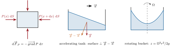
The resultant of the pressure forces exerted by the surrounding fluid on a particle of volume is
pressure acts as a volume force of density , pushing from high toward low pressure.
Proof. On the box of Theorem 2.8, the faces at and receive and along : net ; likewise for and . ∎
Definition 3.2 (Perfect fluid)
A perfect fluid is one in which the only contact force between neighbouring particles is the pressure — normal to every surface, no tangential (viscous) stress. It is an idealization valid, as the next chapter explains, far from walls and at high Reynolds number: water in a pipe away from the wall, air around a wing outside the thin boundary layer, a wave on the sea.
Theorem 3.3 (Euler’s equation)
In a Galilean frame, a perfect fluid of density subject to gravity obeys, at every point,
to which any other volume force density (electric, inertial in a non-Galilean frame) is added on the right. At rest it reduces to the hydrostatic law of the Year 1 volume.
Proof. Newton’s second law for the particle of mass : its acceleration is the material derivative (Theorem 2.4), the forces are the pressure resultant and the weight ; divide by . ∎
Example 3.4 (A tank that accelerates)
Water in a tank carried by a truck accelerating at is at rest in the truck’s frame; there, Euler with the inertial force gives : the pressure grows along the "effective gravity" , the free surface (an isobar) is perpendicular to it and tilts backward by the angle — for . In a bucket spinning at , the centrifugal force gives and the free surface is the paraboloid .
3.2 Bernoulli’s theorem
Theorem 3.5 (Bernoulli)
For a perfect, incompressible fluid of uniform density in steady flow, in a Galilean frame with uniform gravity, the quantity
is constant along each streamline. If the flow is moreover irrotational, it is the same constant throughout the fluid. The term is the dynamic pressure; is the stagnation pressure, the pressure the fluid would reach if brought to rest along its streamline.
Proof. Steady Euler with and , uniform:
The right side is perpendicular to , so the gradient of the Bernoulli quantity has no component along the streamline: the quantity is constant along it. If the gradient vanishes everywhere. ∎
Remark 3.6 (What Bernoulli says and does not say)
Divided by , the theorem reads: the mechanical energy per unit mass, , plus is conserved along a particle’s path. The pressure term is the work done on the particle by the pressure of the fluid behind it, minus the work it does on the fluid ahead: the energy theorem for a particle pushed through a pressure field without friction. Four conditions: perfect fluid (no viscous loss), steady, incompressible, and along a streamline. Comparing two points on different streamlines is allowed only in irrotational flow. It does not say "fast air sucks": it says that a particle that has been accelerated (by a pressure drop) is now at lower pressure — the cause is the pressure field, the speed is the effect.
Remark 3.7 (Compressible fluids)
For a gas the density varies, but if the flow is steady, perfect and isentropic the same proof gives the conservation of along a streamline, where is the enthalpy per unit mass ( for a perfect gas): the form used for nozzles and turbines in Chapter 27. At speeds well below the speed of sound ( in air) the density changes by less than and the incompressible theorem is accurate.
3.3 Applications
Proposition 3.8 (The Venturi meter)
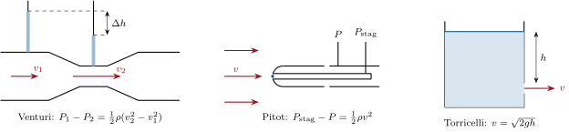
In a horizontal pipe narrowing from section to , the speed rises (, mass conservation) and the pressure drops:
Measuring the pressure difference with a manometer gives the flow rate: a Venturi meter. The same effect drives a carburettor, a paint spray, a Bunsen burner’s air intake and the "suction" of a passing train.
Proof. Bernoulli along a central streamline at constant height, with ; solve for . ∎
Proposition 3.9 (The Pitot tube)
A tube facing the flow, closed at the far end, brings the fluid to rest at its mouth (a stagnation point); a second opening on the side, parallel to the flow, reads the static pressure . The difference is the dynamic pressure:
Every aircraft measures its airspeed this way.
Proof. Bernoulli along the streamline that ends at the stagnation point, where ; the side holes do not disturb the flow, which passes at the undisturbed and . ∎
Proposition 3.10 (Torricelli’s formula)
A large open tank drains through a small hole at depth below the free surface; the jet leaves at
the speed of free fall from the surface. The flow rate is with the hole’s area and the contraction coefficient of a sharp-edged orifice (the streamlines keep converging past the hole).
Proof. Bernoulli from the free surface (at rest, since the tank is large: ; pressure ) to the jet (pressure just outside the hole): . The flow is quasi-steady: varies slowly. ∎
Example 3.11 (Numbers)
A Venturi of narrowing to on a water pipe, with of water (): , . An airliner at () at : dynamic pressure , of the ambient pressure — the Pitot tube still works, with a compressibility correction. A water tower above the taps: when closed, a jet at if opened wide (in practice far less: the pipes are not perfect).
Proposition 3.12 (Lift on a wing)
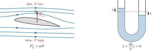
In the flow around a wing the air passes faster over the upper surface than under the lower one; the pressure is therefore lower above than below, and the resultant is the lift ( the wing area, – the lift coefficient, depending on the profile and the angle of attack). The speed difference is equivalent to a circulation of the velocity around the profile, and the lift per unit span is (Kutta–Joukowski, admitted). A spinning ball drags air round with it and is lifted sideways the same way: the Magnus effect of a sliced tennis ball or a curving free kick.
Proof. Bernoulli on the streamlines just above and below, which start from the same upstream conditions: ; integrate over the chord. Why the upper flow is faster — the sharp trailing edge forces the rear stagnation point there and fixes the circulation (the Kutta condition) — is beyond the perfect-fluid model alone; it needs the boundary layer of the next chapter. ∎
Proposition 3.13 (An unsteady flow: the U-tube)
A liquid column of total length fills a U-tube of uniform section; displaced by from equilibrium, it oscillates with
like a pendulum of length . More generally, for an unsteady but irrotational flow with potential , Euler integrates to , the same constant throughout the fluid (unsteady Bernoulli).
Proof. The speed is uniform along the tube (incompressible, uniform section). Project Euler on the tube’s axis and integrate along the column from one free surface to the other: the pressure terms cancel ( at both ends), , the convective term vanishes (same speed at both ends), and the gravity term gives . Hence . The general statement follows from for . ∎
Example 3.14 (Starting a pipe)
A horizontal pipe of length leads from a reservoir of constant head to an open end; the valve is opened at . With uniform along the pipe, Euler integrated from the reservoir surface to the outlet gives , whose solution is with : the flow reaches Torricelli’s speed with the time constant — for a penstock under of head.
Method 3.15 (Using Bernoulli)
(1) Check the four conditions; decide whether the flow is irrotational (uniform upstream flow around an obstacle: yes; flow in a pipe with a velocity profile: no — stay on one streamline). (2) Choose two points on a streamline where as many quantities as possible are known: a free surface (, if the section is large), a jet in the open air (), a stagnation point (). (3) Add mass conservation const to relate the speeds. (4) For unsteady flows, integrate Euler along the line instead.
3.4 Exercises
Exercise 3.1 ★
Water flows in a horizontal pipe of diameter at and pressure . It passes into a section: speed and pressure there; into a section: pressure — what happens if it would come out negative?
Solution
Solution of Exercise 3.1.
, . At : , — close to the vapour pressure. A negative result means the assumed flow rate is impossible: the water cavitates and the flow is throttled.
Exercise 3.2 ★
The Pitot tube of an aircraft at () reads a dynamic pressure of . True airspeed. The airspeed indicator is calibrated for sea-level density (): what "indicated airspeed" does it show, and why do pilots find the difference useful rather than annoying?
Solution
Solution of Exercise 3.2.
; indicated . The indicated airspeed measures the dynamic pressure, which is what the wing feels: the stall speed is a fixed indicated speed at any altitude.
Exercise 3.3 ★
A tank holds water deep; a hole is pierced above the floor. Exit speed; flow rate (contraction ); where does the jet hit the floor? At what depth should a second hole be pierced to reach the same point?
Solution
Solution of Exercise 3.3.
Depth : ; ; fall time , range . Range is symmetric in : a hole at depth ( above the floor) hits the same point.
Exercise 3.4 ★
A wind of blows over a flat roof of ; the air under the roof is still at atmospheric pressure (). Pressure difference and net force on the roof; compare with the weight of the roof (). Which way is it pushed?
Solution
Solution of Exercise 3.4.
, outside pressure lower: net force upward; the roof weighs : it lifts off. (Real roofs fail at their edges first, where the flow separates.)
Exercise 3.5 ★★
A closed rectangular tank long, half full of water, sits on a truck. (a) Accelerating at : angle of the free surface, and the difference of water height between the rear and the front walls. (b) Pressure difference between the two bottom corners. (c) Braking at — does the water reach the lid above the bottom? (d) Same truck going round a bend of radius at : tilt of the surface.
Solution
Solution of Exercise 3.5.
(a) , ; (higher at the rear). (b) . (c) , difference : the front rises above the mean : , it hits the lid. (d) : , outward side higher.
Exercise 3.6 ★★
A bucket of radius containing water deep is spun about its axis at . (a) Shape and equation of the free surface. (b) Height difference between rim and centre. (c) Volume being conserved, height of the water at the centre and at the rim. (d) At what rotation rate does the bottom centre dry out? (e) Why does the same paraboloid make a perfect telescope mirror (a spinning pool of mercury)?
Solution
Solution of Exercise 3.6.
(a) Paraboloid , . (b) . (c) The mean height of a paraboloid over the disk is halfway: centre , rim . (d) Centre dry when : turns per second. (e) A paraboloid focuses parallel rays to one point, at ; liquid-mirror telescopes spin mercury.
Exercise 3.7 ★★
Siphon. A tube carries water from a tank over a crest above the free surface to an outlet below it. (a) Exit speed and, for a tube, flow rate. (b) Pressure at the crest. (c) Maximum height of the crest for the siphon to work (the water’s vapour pressure, , must not be reached). (d) Why does the siphon not work with the tube full of air?
Solution
Solution of Exercise 3.7.
(a) ; . (b) . (c) : . (d) Air is compressible and light: no continuous liquid column to transmit the pressure, the water on both sides just stays.
Exercise 3.8 ★★
A light aircraft of cruises at at sea level on a wing of . (a) Mean pressure difference between the two faces of the wing; lift coefficient. (b) If the speed under the wing is , what is it over the wing (take the same upstream conditions)? (c) Circulation around the profile from the Kutta–Joukowski formula, for a span of . (d) Stalling speed if cannot exceed .
Solution
Solution of Exercise 3.8.
(a) ; , . (b) : . (c) : . (d) .
Exercise 3.9 ★★
Stenosis. Blood () flows at in an artery of section at above atmospheric pressure. A plaque narrows it to . (a) Speed and pressure in the stenosis. (b) The tissue outside the artery is at about : can the artery collapse? (c) If it narrows, the speed rises further: explain the runaway and why such a narrowing can flutter.
Solution
Solution of Exercise 3.9.
(a) ; , . (b) Still above : no. (c) At , and : , below the tissue pressure — the wall collapses, the flow stops, the pressure recovers, it reopens: a flutter (the murmur a physician hears).
Exercise 3.10 ★★★
Stagnation temperature. For a perfect gas in steady isentropic flow, is conserved along a streamline. (a) Show that the air brought to rest at the nose of an aircraft reaches , with the Mach number and the speed of sound. (b) Nose temperature of an airliner at in air at ; of a supersonic aircraft at ; of a re-entry capsule at (is the formula still meaningful?). (c) Show that the incompressible Pitot formula overestimates the speed at , and by roughly how much (expand to second order in ).
Solution
Solution of Exercise 3.10.
(a) with and : . (b) : ; : ; : — meaningless: the air dissociates and ionizes, is not constant (real stagnation temperatures are several thousand kelvin). (c) , and : . Reading from overestimates it by at .
Exercise 3.11 ★★★
Starting transient. A pipe of length and uniform section leads from a large reservoir (head above the outlet) to a valve at the open end. The valve is opened at . (a) Integrate Euler along the pipe to get . (b) Solve it: with . (c) Time to reach of the final speed. (d) The valve is now shut abruptly in from full flow: estimate the mean deceleration and the over-pressure at the valve from — and why a real closure produces far more (next chapters).
Solution
Solution of Exercise 3.11.
(a) From the surface (, , height ) to the outlet (, , height ), with . (b) , : . (c) ; at : . (d) : . Water is slightly compressible: a fast closure launches a pressure wave, .
Exercise 3.12 ★★★
The free surface of a vortex. Water rotates as the point vortex of Chapter 2, , irrotational, with a free surface at far away. (a) Why may Bernoulli be applied between any two points? (b) Shape of the free surface . (c) Inside a Rankine core (, , rotational) use instead Euler in the rotating frame or directly: show . (d) Total depth of the funnel for a bathtub vortex with and ; for a tornado (, , in air: express the result as a pressure drop at the centre instead).
Solution
Solution of Exercise 3.12.
(a) Steady, perfect, incompressible and irrotational: one constant for the whole flow. (b) On the surface : , . (c) Radial Euler: , vertical hydrostatics: the surface satisfies . (d) Bath: ; , and the core adds another : deep. Tornado: outside plus the same inside: below ambient at the centre.
3.5 Problem: The dam, the penstock and the turbine
Problem 3.1
Weekend problem — a hydroelectric plant from the reservoir to the jet: pressures, speeds, powers, losses and the water hammer
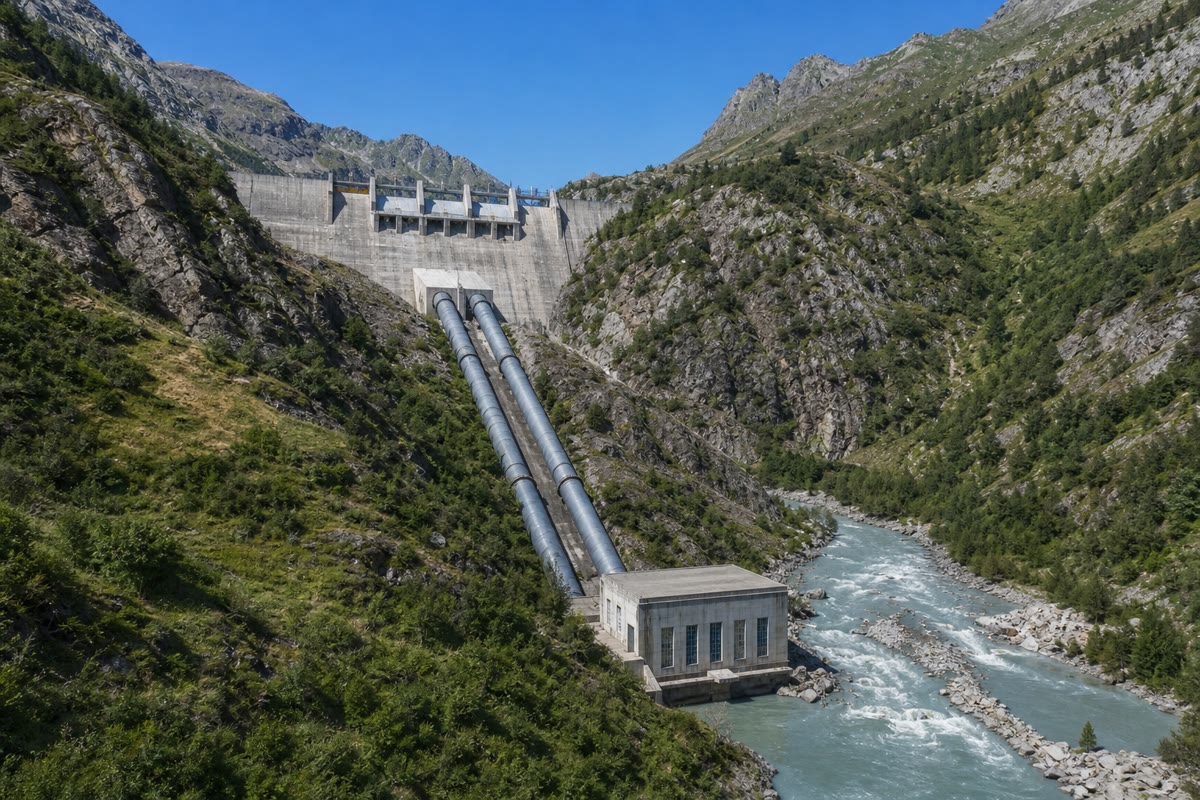
A reservoir holds water deep behind a dam; its free surface is above the nozzles of a turbine. A penstock (a steel pipe) of diameter and length carries the design flow down to the turbine house, where a nozzle turns it into a free jet at atmospheric pressure which strikes the buckets of a Pelton wheel. , ; the fluid is perfect unless stated otherwise.
Part I — At rest and at design flow.
- Pressure at the base of the dam, and the force on a -wide vertical strip of the dam from top to bottom.
- With the turbine valves closed, pressure in the penstock at the turbine house.
- Speed in the penstock at design flow; dynamic pressure there; pressure at the turbine house end of the penstock (before the nozzle), by Bernoulli from the reservoir surface.
- Speed of the free jet; section and diameter of the nozzle.
- Kinetic power carried by the jet; show it equals and compute it.
- Mass and kinetic energy of the water contained in the penstock at design flow; transit time of a particle down the pipe.
- Show that the head is shared, at design flow, between the pressure at the bottom of the penstock and the kinetic energy of the water, and that the nozzle converts the first into the second: what is the pressure just after the nozzle?
- A perfect fluid has no head loss, a real one does: the loss in a pipe is with for smooth steel. Head loss in metres of water, and the fraction of the power lost.
- An engineer proposes a penstock to save steel. Redo question 7; comment.
Part II — Measuring the flow. A Venturi is built into the penstock, with a throat of .
- Speed at the throat and pressure drop between the pipe and the throat at design flow.
- The drop is read on a mercury manometer (): height difference.
- Show that the flow rate is proportional to the square root of the manometer reading, and give the reading at half the design flow.
- Why must the pressure taps be flush with the wall and not protrude into the flow?
- A section of the pipe runs, for topographic reasons, over a crest above the reservoir surface. Pressure there at design flow; what happens, and what must the designer do?
Part III — Unsteady regimes. The reservoir has a surface area .
- Rate at which the reservoir level falls at design flow, in centimetres per hour.
- The turbine is stopped and the nozzle (section from question 4) is left open to the air: the reservoir drains by gravity. Write the mass balance and find the level (quasi-steady Torricelli flow).
- Time for the level to fall by ; compare with the time at constant design flow.
- Starting the plant: the penstock is full, the nozzle is opened at . Taking the speed uniform along the penstock and neglecting the nozzle’s geometry, integrate Euler along the pipe to obtain , solve it, and give the time constant.
- During this start-up, at the instant when is half its final value, what is the pressure at the bottom of the penstock? Explain the sign of the difference with the steady value.
Part IV — Closing the valve.
- The valve at the turbine is shut in ; assume the water in the penstock decelerates uniformly. Using Euler along the pipe, estimate the over-pressure at the valve, in bars.
- For a fast closure the water is not incompressible: a pressure wave travels up the pipe at (the speed of sound in water in a steel pipe — Chapter 7), and the over-pressure is (Joukowsky). Value for a sudden stop from design flow; compare with the static pressure. How long does the wave take to reach the reservoir and back, and what does that say about the meaning of "fast"?
- To protect the penstock a surge tank — a vertical open shaft of section — is connected where a horizontal tunnel of length and section from the reservoir joins the penstock. After a sudden closure, the water in the tunnel keeps moving and the level in the shaft rises. Write mass conservation between the tunnel and the shaft.
- Integrate Euler along the tunnel (perfect fluid) to show that obeys ; period of the oscillation.
- Maximum rise of the level in the shaft after a closure from design flow (energy argument: the kinetic energy of the tunnel water becomes potential energy in the shaft).
- Sum up: the five pressures met in this plant (static at the dam, static at the turbine, dynamic in the pipe, water hammer, surge) and the law that gives each.
Solution
Solution of Problem 3.1.
1. above atmospheric; .
2. gauge, absolute.
3. ; ; absolute.
4. ; , .
5. .
6. , ; transit .
7. : of pressure and of kinetic energy; in the nozzle the pressure falls to while rises to : just after it, .
8. , of the power.
9. , , : lost — the saving in steel is paid every second in energy.
10. ; .
11. : .
12. : ; half the flow gives a quarter, .
13. A protruding tap faces or disturbs the flow and reads part of the dynamic pressure (a Pitot), not the static pressure.
14. : near the vapour pressure, dissolved air comes out and the water may boil (cavitation), breaking the column. Lower the crest, or fit an air valve and a vacuum pump, or reduce the flow.
15. .
16. : .
17. ; at constant design flow : nearly the same, the nozzle having been sized for Torricelli’s flow at .
18. : , , time constant .
19. At : ; : most of the head is busy accelerating the column, so the pressure at the bottom is far below its steady value.
20. : .
21. , six times the static pressure. The wave’s round trip is : a closure faster than that is "sudden" and gets the full Joukowsky over-pressure; slower closures get less.
22. .
23. Euler along the tunnel, from the reservoir (pressure depth) to the foot of the shaft (pressure ): ; with : ; .
24. with : .
25. Dam: hydrostatics, . Turbine, valves closed: the same, . Penstock in operation: Bernoulli, taken from the static head. Water hammer: compressibility, . Surge: unsteady Euler along the tunnel, an oscillation of period .