University Physics — Year 2 · Bachelor Year 2
16Guided Waves and Cavities
A radar’s pulse travels from the transmitter to the dish inside a rectangular copper pipe; the light of an internet link travels ten thousand kilometres inside a glass thread thinner than a hair; the microwaves of an oven bounce between its walls and settle into a pattern of hot and cold spots. A wave confined by conducting or refracting walls is no longer a plane wave free to go anywhere: it must satisfy the boundary conditions on the walls, and that selects the shapes it may take — the modes — and forbids it below a cut-off frequency. This chapter builds the simplest guide, two parallel conducting plates, from the reflections of Chapter 15; then the rectangular waveguide, the closed cavity, and, in the ray picture, the optical fibre.
16.1 Waves between two conducting plates
Proposition 16.1 (Modes of the parallel-plate guide)
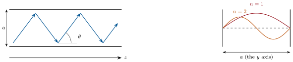
Two perfectly conducting planes and bound a vacuum. Seek a wave travelling along with (the field parallel to the plates, perpendicular to the propagation). Maxwell’s equations in vacuum and the condition on the plates impose
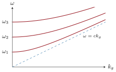
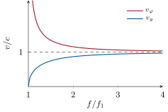
Mode propagates only above its cut-off frequency ; below, is imaginary and the field decays along the guide. Its phase and group velocities are
and its magnetic field has components along and along : a guided wave is not transverse in the direction of propagation.
Proof. Insert in : , i.e. , whose solutions vanishing at and are the sines with ; holds since does not depend on . Faraday gives and , the latter in quadrature. The velocities follow from the Klein–Gordon form of the dispersion relation (Chapter 8). ∎
Remark 16.2 (The mode as two plane waves)
is the sum of two plane waves with wavevectors , of modulus , bouncing between the plates at the angle from the axis with : a guided mode is a plane wave zigzagging between the walls, reflected with at each one, the transverse standing wave being the condition that it interferes constructively with itself. The energy travels along the zigzag at , hence along the axis at ; the crests’ intersections with the axis run at . At cut-off the wave bounces back and forth across the guide and goes nowhere.
Example 16.3 (Numbers)
Plates apart: , ; between those frequencies only one mode propagates (single-mode operation, which keeps a pulse from splitting into several with different ). At the mode has , , and the guide wavelength instead of in free space. At nothing passes: the field decays as with — the principle of the mesh in an oven door, of the waveguide below cut-off used as a calibrated attenuator, and of the metal ducts of ventilation that let air but no radio through.
16.2 The rectangular waveguide and the cavity
Proposition 16.4 (The rectangular guide; the TE mode)
A hollow metal pipe of rectangular section () carries modes whose cut-off frequencies are
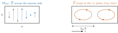
the lowest, the TE mode (), has : one half-sine across the wide side, uniform across the narrow side, vanishing on the two walls , — exactly the parallel-plate mode, the side walls , being perpendicular to and imposing nothing on it. The guide is used between and the next cut-off; its magnetic field lines close in the plane and the currents they induce in the walls are what a slot must not cut. The power carried is .
Proof. The general mode is / products in and with the boundary conditions on the four walls, giving (admitted in general; the TE case is the proposition above). Power: the mean Poynting vector along is integrated over the section. ∎
Proposition 16.5 (Cavity resonator)
Closing a guide with two conducting walls a length apart turns it into a cavity, in which the guided wave must form a standing wave along too: , and the resonance frequencies of a rectangular box are
The number of modes with frequency below grows as for a box of volume (admitted: count the points of the lattice in an eighth of a sphere, with two polarizations) — the density of modes that the theory of thermal radiation will need (Chapter 26). Each mode has a quality factor set by the wall losses (the surface resistance of Chapter 14), typically – for copper at microwave frequencies, for a superconducting cavity.
Proof. Standing waves along the three directions with nodes on the six walls; the wavevector has modulus . ∎
Example 16.6 (Ovens, radars, clocks)
A microwave oven of cm near has dozens of modes within a few percent of the magnetron’s frequency: the field is a superposition of standing waves, with maxima apart, which the turntable (and a "mode stirrer") smooth out. A radar’s magnetron is itself a cavity resonator; a particle accelerator is a chain of superconducting cavities whose TM mode pushes the bunches; the atoms of a caesium clock cross a microwave cavity tuned to .
16.3 The optical fibre in the ray picture
Proposition 16.7 (Step-index fibre)
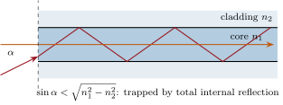
A glass core of index surrounded by a cladding of slightly lower index guides light by total internal reflection at the core boundary. A ray entering the end face from air at the angle from the axis is trapped if , the numerical aperture; rays of different angles travel different lengths, and a pulse entering a fibre of length is spread by
the modal dispersion — some per kilometre for , which limits a multimode fibre to a few megabits per second over ten kilometres. A single-mode fibre has a core so thin () that only one mode propagates, like the guide between its first two cut-offs; what remains is the chromatic dispersion of the glass (Chapter 8).
Proof. Total reflection at the core–cladding interface needs for the angle from the normal to the boundary, i.e. for the angle from the axis inside; refraction at the entrance gives , whence . The steepest trapped ray travels against for the axial one, at . ∎
Method 16.8 (Guided-wave bookkeeping)
(1) Identify the walls and their condition (tangential on a conductor; total reflection for a dielectric). (2) Write the field as a transverse standing wave times a progressive factor along the guide; the boundary conditions quantize the transverse wavenumber. (3) The dispersion relation gives the cut-off, , , . (4) Count the propagating modes at the working frequency; aim for one. (5) For a cavity add the longitudinal condition and find the resonance frequencies; for the losses use the surface resistance.
16.4 Exercises
Exercise 16.1 ★
Plates apart: cut-off frequencies of the first three modes; at , which modes propagate, and for the first one , , , ; at , the decay length of the field.
Solution
Solution of Exercise 16.1.
, , . At only : , , , . At : .
Exercise 16.2 ★
A standard X-band waveguide has , . Cut-off of TE, of TE and TE; the single-mode band; at : , , the angle of the zigzag. Why is a good choice?
Solution
Solution of Exercise 16.2.
TE , TE , TE : single mode from to . At : , , , , . keeps TE above TE (the widest single-mode band) while leaving the largest gap for the field (power before breakdown).
Exercise 16.3 ★
A cavity of cm: frequencies of the modes , , , ; number of modes below from the counting formula; the lowest mode of a cubic cavity — its side.
Solution
Solution of Exercise 16.3.
: , , , . . Cube: , .
Exercise 16.4 ★
A fibre has , . Numerical aperture and acceptance half-angle; modal spread per kilometre; maximum bit rate over if one bit must last longer than the spread; the same with .
Solution
Solution of Exercise 16.4.
, ; ; over : ; with : , .
Exercise 16.5 ★★
For the parallel-plate mode : (a) find from Faraday’s law and show it has a component in quadrature with . (b) Surface current on each plate (boundary relation). (c) Mean Poynting vector along and the power per unit width; check that its transverse component averages to zero. (d) Show that the energy velocity, power over mean energy per unit length, equals .
Solution
Solution of Exercise 16.5.
(a) , : in quadrature. (b) At , and : along the field. (c) , power per unit width ; . (d) Mean energy per unit length and width (electric and magnetic halves each ); the ratio is .
Exercise 16.6 ★★
Below cut-off. (a) A hole in the mesh of an oven door at : treat it as a guide of width ; decay length and attenuation across the sheet in dB (compare Chapter 14). (b) A ventilation duct of section in a shielded room: up to what frequency does it block radio, and by how much does it attenuate over ? (c) A "waveguide-beyond-cutoff attenuator" uses a tube of diameter at : attenuation per centimetre (use the plate formula with as an estimate). (d) Why is the attenuation independent of the wall conductivity?
Solution
Solution of Exercise 16.6.
(a) : ; : in amplitude, in power. (b) ; at : over a metre. (c) , : . (d) The wave does not fit; evanescence is geometry, not dissipation.
Exercise 16.7 ★★
Power and breakdown. The X-band guide of Exercise 16.2 carries TE at . (a) Power for . (b) Air breaks down at : maximum power; how do radars carry megawatts (pressurization, gases)? (c) Wall losses: the surface current at the broad wall is of order ; with for copper at , estimate the loss per metre and the attenuation in dB/m. (d) Compare with a coaxial cable’s : why are guides used at these frequencies?
Solution
Solution of Exercise 16.7.
(a) . (b) : ; pressurized nitrogen or SF raise the breakdown field. (c) ; over per metre: , per metre, about . (d) Three times less than the cable, and megawatts instead of kilowatts.
Exercise 16.8 ★★
Cavity quality. A copper cubic cavity of side in its lowest mode. (a) Frequency. (b) The stored energy is (admitted) and the wall loss area with and : quality factor — compute it. (c) Bandwidth of the resonance; ring-down time . (d) A superconducting cavity has : , and why accelerators use them.
Solution
Solution of Exercise 16.8.
(a) . (b) , ; ; : . (c) ; . (d) : the field of tens of megavolts per metre is sustained by kilowatts instead of gigawatts.
Exercise 16.9 ★★
Mode counting. (a) Show that the number of modes of a box of volume with frequency below is (points in the eighth of a sphere of radius for a cube, two polarizations). (b) The number of modes per unit volume and frequency, . (c) A room: modes per hertz at ; at (visible light). (d) Why does a small cavity have sparse modes while a big room has a continuum — and what is the oven’s case at ?
Solution
Solution of Exercise 16.9.
(a) Points with fill an eighth of a sphere: , times two polarizations: . (b) . (c) per hertz (one per megahertz) at ; per hertz at . (d) Modes are discrete when their spacing exceeds their width; in the oven, one mode per or so around — dozens within a few percent.
Exercise 16.10 ★★★
TE in full. In the guide , : . (a) From Faraday, find and ; check . (b) Check Maxwell–Ampère in vacuum, and recover . (c) Surface currents on the four walls (the broad walls , and the narrow walls , ); which currents flow along , which across? (d) A slot cut along in the centre of a broad wall does not radiate, a slot across it does: explain.
Solution
Solution of Exercise 16.10.
(a) From :
and . (b) : . (c) Broad walls: — along as , across as (zero at the centre); narrow walls: along only. (d) A central longitudinal slot cuts only transverse currents, which vanish there; a transverse slot cuts the longitudinal ones and radiates: the slotted-waveguide antenna.
Exercise 16.11 ★★★
Dielectric guide. A slab of index and thickness in a medium guides light by total reflection. (a) For a ray at angle from the normal to the faces, the guided condition is that the round-trip phase across the slab, ( the phase shift of total reflection, taken here), is a multiple of : number of modes for , , , (admit the mode count per polarization). (b) Thickness for a single mode. (c) Compare with a single-mode fibre core of . (d) Why can the dielectric guide, unlike the metal one, not have a cut-off for its lowest mode?
Solution
Solution of Exercise 16.11.
(a) per polarization. (b) . (c) A round core with is single-mode below : the standard. (d) A grazing ray is always totally reflected: the lowest mode exists at every frequency, its evanescent tails merely spreading into the cladding.
Exercise 16.12 ★★★
Graded-index fibre. To reduce modal dispersion the core index decreases from the axis outward, with . (a) Explain qualitatively why an off-axis ray, though longer, can take the same time as the axial one. (b) Using the ray equation in a stratified medium, const, show that a ray launched from the axis at a small angle oscillates sinusoidally about it (expand to second order). (c) Period of the oscillation for . (d) The residual modal spread is of order : value per kilometre, compared with the step-index .
Solution
Solution of Exercise 16.12.
(a) The off-axis ray spends its time in lower index, where light is faster: the longer path is compensated. (b) with and : , a harmonic oscillation . (c) . (d) against : two hundred times better.
16.5 Problem: The oven cavity and the optical fibre
Problem 16.1
Weekend problem — two guided-wave systems in every kitchen and every city: the oven that cooks with standing waves and the fibre that carries the internet
Part I — From the magnetron to the cavity. A magnetron feeds at into a rectangular waveguide (, ) that opens into the oven cavity ( cm); walls steel, .
- Cut-off frequencies of the guide’s TE, TE, TE modes; check that only TE propagates at .
- Guide wavelength, phase and group velocities at .
- Field amplitude in the guide for (TE power formula); compare with the breakdown field of air.
- Surface current amplitude on the broad wall (of order ); skin depth and surface resistance of the steel; loss per metre of guide.
- Modes of the cavity: list those with frequencies within of (try up to ); how many?
- Distance between the hot spots of one such mode along each axis; why does the plate turn, and what is a "mode stirrer"?
- The cavity’s quality factor when loaded with food is about : bandwidth of its response; why a mismatch between the magnetron’s frequency and the modes does not matter much.
- The empty cavity has : stored energy at input, mean energy density, field amplitude; compare with question 3 and with breakdown. What protects the magnetron when the oven runs empty?
- Time for the energy to travel the of guide from the magnetron to the cavity.
- The magnetron is fed by a half-wave rectified supply and emits only during half of each mains cycle: peak power during the bursts for a mean of ; what does the cavity do between bursts (use )?
Part II — The door and the cut-off.
- The door mesh has holes in a sheet: decay length in a hole and attenuation in dB across the sheet.
- The door’s edge is sealed by a quarter-wave "choke": a slot deep around the door frame, which presents an open circuit at the gap (recall Chapter 15): depth of the slot at .
- Legal leakage is at : to what fraction of through a door does that correspond?
- A duct of diameter vents the cavity: is it below cut-off at ? Attenuation over its length.
- Why must the mesh be electrically bonded to the door frame all round (what would a gap in the bond behave like)?
Part III — The fibre. A step-index fibre: core , cladding , core diameter (multimode) or (single-mode); ; attenuation .
- Numerical aperture and acceptance angle; is it easy to couple light in?
- Modal spread per kilometre for the multimode fibre; maximum bit rate over (one bit per spread time).
- Number of modes of the multimode fibre (admit ); of the single-mode one (: show the same formula gives about ).
- In the single-mode fibre the remaining spreading is chromatic: with (Chapter 8) and pulses, distance over which a pulse doubles; bit rate over .
- Attenuation over in dB and as a power ratio; input : output power; with amplifiers every , how many for a transatlantic link?
- Frequency and photon energy at ; photons per second in , and per bit at , at the input and after .
- Why (think of the two loss mechanisms of silica: Rayleigh scattering, falling as , and infrared absorption rising beyond )?
- Fresnel reflection at a cleaved fibre end facing air: loss in dB; why connectors use index-matching gel or polished physical contact.
- Why does a fibre not radiate at a gentle bend, and why does it lose light at a sharp one (think of the angle of the ray on the core boundary)?
- Compare the two guides of this problem: what confines the wave, what limits the bandwidth, what the losses.
Solution
Solution of Problem 16.1.
1. ; TE and TE: : only TE at .
2. : , , .
3. : , a hundredth of breakdown.
4. ; , ; : per metre — steel is lossy, the guide is short.
5. within of : , at , , , , at — about six.
6. Half-wavelengths , , : to apart. The turntable drags the food through maxima and minima; a stirrer (a rotating metal fan) reshuffles the modes.
7. : the loaded resonances overlap into a continuum; the magnetron always finds a mode to feed.
8. ; ; — near breakdown: arcs; the reflected power goes back to the magnetron, protected (a little) by a dummy load or circulator — hence "never run it empty".
9. .
10. peak; between bursts the field rings down in : the cavity is empty most of the time.
11. ; : in amplitude, in power.
12. .
13. = : .
14. : below cut-off; , : .
15. The wall currents must flow continuously into the mesh; a gap in the bond is a slot that cuts them — a slot antenna radiating outward.
16. , : a narrow cone, needing a laser and a lens.
17. ; over : .
18. ; for : — the single-mode regime ().
19. : , : over that distance before compensation.
20. , a factor : ; amplifiers.
21. , ; photons per second; per bit at the input, after .
22. The sum of the two losses is minimal near ().
23. : per face, twice at a connector plus the gap’s interference; gel or physical contact removes the air.
24. On a gentle bend the ray still meets the boundary beyond the critical angle; on a sharp one the incidence on the outer wall falls below it and light leaks out.
25. Oven: metal walls, reflection with ; bandwidth set by the cavity’s modes; losses in the steel skin. Fibre: total internal reflection at a glass–glass boundary; bandwidth set by modal and chromatic dispersion; losses by scattering and absorption, .